34008030EN/AD - Page 17
2. Installation
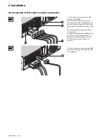
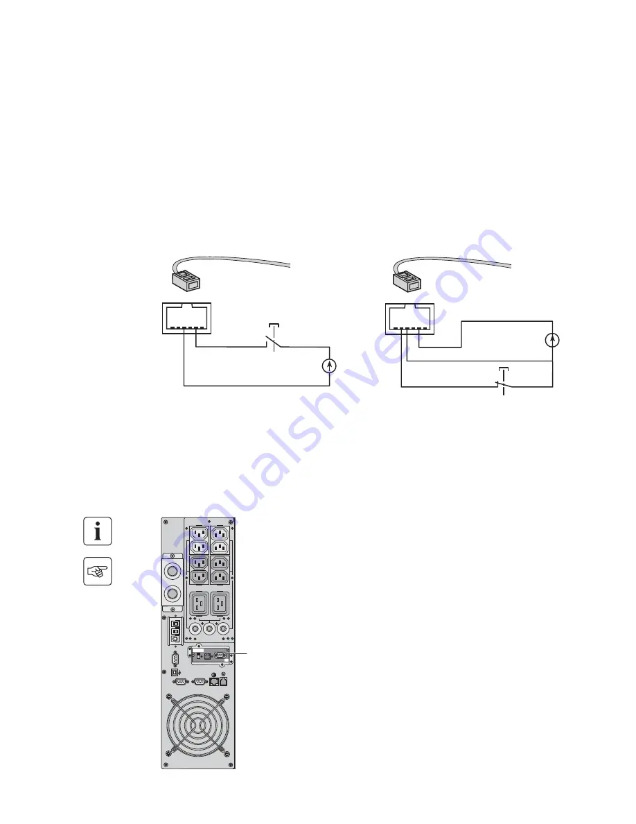
Remote Power Off communication port (16)
(see page 8)
Installation of communication cards
(optional, standard with the NetPack version)
Installation of a Remote Power Off function must be carried out in compliance with applicable regulations.
In order to fully de-energize devices and
MX RT
with the RPO port, it is necessary:
◗
to use a two-position switch (Normally Open or Closed contact should be held more than 1 second to be taken into
account).
◗
to connect to this RPO switch a device that allows to trip all breaker(s) located
upstream
(1)
and
downstream
(2)
MX
RT
. This can be achieved by means of a shunt trip.
(1): If not, the output devices could be powered again through static switch when the two-position switch is released.
(2): If not, the output devices will remain powered several seconds after the RPO activation.
Please, notice that the internal batteries will remain connected to the power sub-module after RPO activation.
The cable is not included.
Remote power off contact normally open
Remote power off contact normally closed
◗
Signal:
- activation voltage: 5 V DC to 27 V DC.
- current: 10 mA max.
Communication card (restricted access)
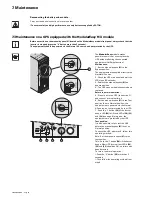
It is not necessary to shutdown the UPS
before installing a communications card.
1 - Remove the slot cover secured by two
screws.
2 - Insert the communications card in the
slot.
3 - Secure the card with both screws.
RJ12 (6p6c)
5 4 3 2 1
6
5 V DC to 27 V DC
5 4 3 2 1
6
RJ12 (6p6c)
5 V DC to 27 V DC
RS232
CONTACTS
RPO
PARALLEL
SWITCHED
GROUP 2
SWITCHED
GROUP 1
Card Settings
RS
232
Download
66
07
4
UPS
data
Reset
1
00
1
0
1 2
ON
ETHERNET
RS
232
IP=
MAC=00E0D8FF8
55
E
BATTERY
DETECTION


