15
Section 3: General operation and circuit breaker description
Series NRX with PXR - type RF low voltage power (air) circuit breakers instruction manual
MN013002ENH03 September 2016 www.eaton.com
Operating mechanism
The series NRX operating mechanism is a two-stage stored
energy trip-free mechanism. Energy is stored for a closing
operation with sufficient energy remaining to open the cir-
cuit breaker after a closing operation.
All circuit breakers should be operated manually and/or elec-
trically before they are put into service. This can be done
during the installation process or some later date prior to
startup. To perform this operational check, follow the proce-
dures outlined in this section.
Manual operation
On manually operated circuit breakers, the closing spring
must be charged by hand. To manually charge the spring
and operate the circuit breaker, proceed with the following
three steps:
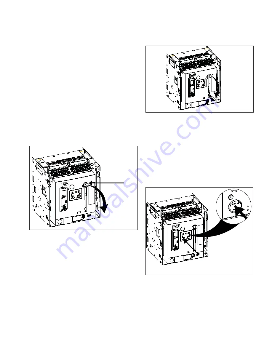
Step 1: Insert one finger in the curved recess behind the
charging handle and pull out and down.
Figure 24. Step 1.
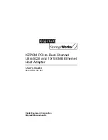
Step 2: It takes approximately seven full downward strokes
to complete the charging process. It is possible to manually
recharge the spring immediately after closing the breaker,
before it has been tripped open. The status of the spring
(charged or discharged) is indicated in the mechanism spring
status window just above the pushbuttons.
Figure 25. Step 2.
Step 3: Standard manually operated circuit breakers are
closed and opened by hand using the Manual ON and
Manual OFF buttons located on the front of the circuit
breaker. To perform either operation, press and release the
appropriate button. Pressing the close button will not close
the breaker unless the Ready-to-Close flag displays ready.
The Ready-to-Close flag is adjacent to the spring status flag.
The Ready-to-Close flag will display not-ready if the breaker
is closed, not fully charged, or held in the tripped state by
an accessory or interlock. The status of the contacts (open
or close) is indicated in the Contact Status Window just
above the pushbuttons on the front of the breaker.
Figure 26. Step 2.


