EATON
Installation & Maintenance Instructions
TM396 – XF-XP-XT LW UL ISS.A
13 |
P a g e
3.4
Electrical Installation
Electrical installation and servicing should only be carried out by qualified service personnel and in
accordance with all local/national codes of practice and standards e.g. UL 1203 Edn. 5, CSA22.2 No30-
M1986 reaffirmed 2014, CSA C22.2 No25-1966 reaffirmed 2014, CSA C22.2 No 60065-03 Edn. 1, UL60065
Edn. 7.
Due to the large number of possible configurations, this manual only covers the standard installation of the
units.
For detailed connection and configuration of units, the installer should refer to individual project specific
drawings and information.
Units can be supplied, as required, with either 24V AC or DC, 110V AC or 230V AC Supply; (±10%). The units
should only be powered from the specified voltage, no allowance is made for varying voltage supply.
WARNING:
IRREPARABLE DAMAGE TO THE UNIT MAY RESULT FROM AN
INCORRECT POWER SUPPLY VOLTAGE
3.4.1 Electrical Installation XP & XT Integrated Pan, Tilt, housing assembly
For safe access to electrical connections with the XP and XT series cameras, caution should be taken when
removing and inserting any entry covers/ flanges/ cable glands to avoid internal cables becoming snagged
or stretched on internal objects and fittings.
WARNING:
THE BASE ENTRY COVER AND GLANDS SHOULD NEVER BE REMOVED WHEN THE UNIT
IS ENERGISED. WAIT 5 MINUTES AFTER DE-ENERGISING.
1.
Always use colour-coded conductors or other identification of conductors for ease of wiring and
identification of function later.
2.
Keep a wiring diagram with the system for later use and reference.
3.
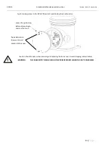
Provision is made for one or two cable entries, at the Base Enclosure of the pan tilt. (Fig.12)
To maintain the certification requirements of the unit all cables/conduits must be fitted at the entry, with
certified Class/ Div Flameproof, compound filled barrier glands, or conduit sealing fittings within 2” or
50mm of the enclosure.
4.
The cable entries to the unit can be either ¾” NPT thread, or ½” NPT using a suitably certified
reducer, depending on order.
5.
A minimum of 5 fully engaged threads must be maintained for all glands.
6.
All unused threaded openings shall be closed by suitably approved threaded plugs, recommended
EBNV/7 approved.
7.
All glands/reducers must be ingress protected to IP67 or better, maintaining the weatherproof
rating of the equipment.
8.
For maintenance purposes, consult the separately supplied (additional) wiring drawings, specific to
the purchase order, for as built wiring/ connection details of the unit.
9.
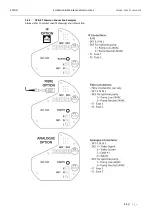
The base unit has accessible input fuses (F1 & F2 see sections 3.4.2 & 3.4.4). Check that the input
fuse matches the voltage requirement:
Fuse 1:
6.3A (24V AC & DC)
2A (≥110)
Fuse 2:
1A


