Understanding UPS Operation
Power Xpert
TM
9395 550/275 UPS (225–550 kVA) Installation and Operation Manual 164201716—Rev 8
www.eaton.com/powerquality
6-19
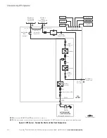
Figure 6-13. Typical Distributed Bypass System (1+1 and 2+0 Configurations)
Battery Breaker
Battery
Converter
Inverter
K3
Fuse
Rectifier
K1
K2
Fuse
Fuse
Fuse
E6
E7
E8
E12
K5
Static
Switch
Fuse
E1
E2
E3
CB1
(optional)
UPS 1
A
B
TIE
CABINET
(Optional)
E
AC Output to
Critical Load
E4. E5
BATTERY SYSTEM
MOB 1
MOB 2
(Not supplied
with the UPS)
C
E9,
E10,
E11,
E12
D
Battery Breaker
Battery
Converter
Inverter
K3
Fuse
Rectifier
K1
K2
Fuse
Fuse
Fuse
E6
E7
E8
E12
K5
Static
Switch
Fuse
E1
E2
E3
CB1
(optional)
UPS 2
A
B
E4. E5
BATTERY SYSTEM
(Not supplied
with the UPS)
C
E9,
E10,
E11,
E12
D
*
*
*
*
A
– AC Input to UPS Rectifier
B
– AC Input to Bypass
C
– DC Input from Battery
D
– UPS AC Output to Tie Cabinet
E
– Output to Critical Load
*
– Overcurrent Protection provided by customer
*
NOTE
This oneline does not show each UPM in the UPSs, but represent
structure of each UPS is shown in Figure 6-5 through Figure 6-8 .
NOTE
If the load requires a neutral, a bypass source neutral must be provided. DO NOT install both a source neutral and a bonding jumper.
Summary of Contents for Power Xpert 9395 550/275
Page 1: ...Power Xpert 9395 UPS 550 275 UPS 225 550 kVA Installation and Operation Manual...
Page 2: ......
Page 3: ...Power Xpert 9395 UPS 550 275 UPS 225 550 kVA Installation and Operation Manual...
Page 27: ...Section 1 Installation...
Page 28: ......
Page 207: ......
Page 208: ...164201716 8 164201716 8...


