Eaton
®
Power Xpert
®
9395P-900 Installation and Operation Manual 164000501—Rev 12
127
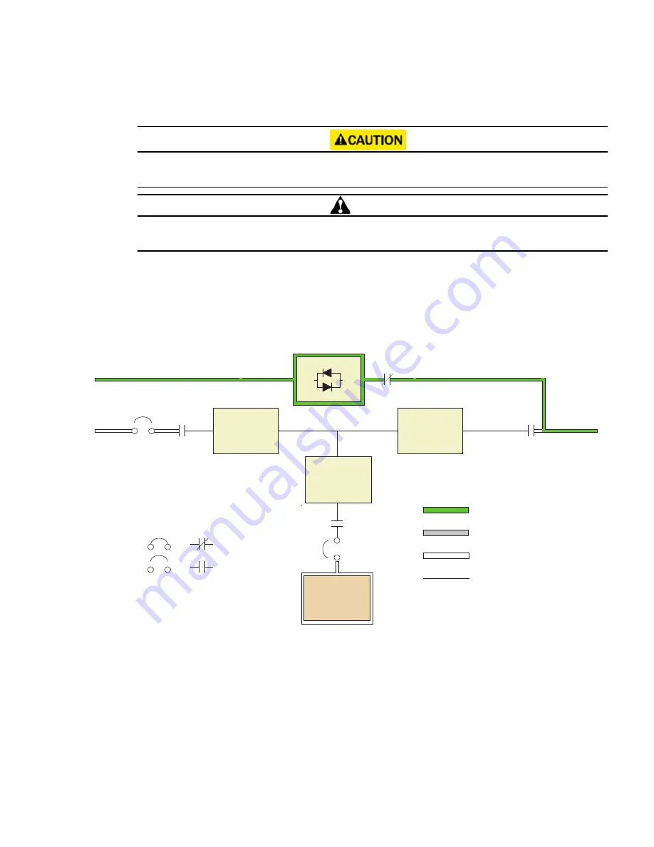
the inverter is unable to support the applied load. The static switch is wired in series with the backfeed
protection contactor, and together they are wired in parallel with the rectifier and inverter.
The critical load is not protected from voltage or frequency fluctuations or power outages while the UPS is in
Bypass mode.
ATTENTION!
Les charges critiques ne sont pas protégées des fluctuations de tension ou de fréquence ni des pannes de
courant lorsque l’onduleur est en mode Contournement.
The static switch, being an electronically-controlled device, can be turned on immediately to pick up the load
from the inverter while the inverter output contactor K3 opens to isolate the inverter. The backfeed protection
contactor is normally always closed, ready to support the static switch unless the bypass input source
becomes unavailable.
Figure 70. Path of Current Through the UPS in Bypass Mode
K1
K3
K5
K1
K3
K2
Main Power Flow
Trickle Current
Energized
De-Energized
Contactors
Breakers
Bypass Input
Rectifier
Input
Input
Breaker
(CB1)
Battery
Breaker
Output
Battery
Closed
Open
Battery
Converter
Rectifier
Inverter
Static
Switch
NOTE
On a UPS configured as an IOM, the bypass input, static switch, bypass breaker (CB4), and K5 are not present.
NOTE
On a UPS configured with a Continuous Static Switch (CSS), bypass breaker (CB4) is not present.
If the UPS transfers to Bypass mode from Online mode due to any reason other than operator intervention, the
UPS automatically attempts to transfer back to Online mode (up to three times within a ten minute period). The
fourth transfer locks the critical load to the bypass source and requires operator intervention to transfer.


