Eaton
®
Power Xpert
®
9395P-900 Installation and Operation Manual 164000501—Rev 12
105
C
Chhaapptteerr 55 IInnssttaalllliinngg O
Oppttiioonnss aanndd A
Acccceessssoorriieess
Read and understand the following notes while planning and performing the wiring installation:
•
Conduit must be installed between the UPS cabinet and the device for signal wiring. Conduit must be
installed between the device and the power source for power wiring. Install the signal wiring in separate
conduit from the power wiring.
•
Conduit and wiring between the UPS and the device are to be supplied by the customer.
•
Maximum distance between the UPS cabinet and the device is not to exceed 150 meters (500 feet).
•
Use Class 1 wiring methods (as defined by the NEC) for interface and power wiring from 30 to 600V.
•
Use Class 2 wiring methods (as defined by the NEC) for interface and power wiring up to 30V. The wire
should be rated at 24V, 1A minimum.
•
Signal wiring should be a minimum of 22 AWG and a maximum of 14 AWG. The wire should be shielded
twisted pair, rated for 5A maximum. Power wiring should be a minimum of 22 AWG and a maximum of 14
AWG. The wire should be rated for 1A minimum.
•
Use only 75°C copper wire.
•
120 Vac for the RMP II, RIM II, or SCM II should be provided from the critical bus by facility planners or the
customer.
Install wiring the optional accessories in accordance with the following paragraphs:
•
Hot Sync CAN Bridge card (see paragraph
Installing an Optional Hot Sync CAN Bridge Card
)
•
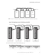
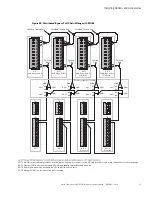
Distributed Bypass Control Wiring (see paragraph
Installing Distributed Bypass Control Wiring
•
RMP II (see paragraph
Installing an Optional Remote Monitor Panel II
•
RIM II (see paragraph
Installing an Optional Relay Interface Module II
)
•
SCM II (see paragraph
Installing an Optional Supervisory Contact Module II
)
55..11
IInnssttaalllliinngg aann O
Oppttiioonnaall H
Hoott S
Syynncc C
CA
AN
N B
Brriiddggee C
Caarrdd
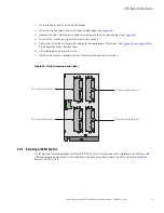
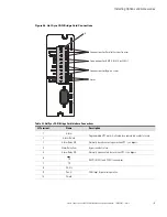
As an option, a Hot Sync Controller Area Network (CAN) Bridge Card, shown in
, can be installed to
provide connectivity for operational mode control of a parallel system. In addition, this card can be used to
connect optional system monitoring devices, such as a Remote Monitor Panel II, a Relay Interface Module II, or
a Supervisory Contact Module II to the UPS.

