INSTALLATION PLAN AND UNPACKING
Power Xpert 9395 Integrated Battery Cabinet (Model 1085 and 1085HR) Installation Manual
S
164201687 Rev 4
www.eaton.com/powerquality
3-8
Battery terminals consist of pressure terminations, UL and CSA rated at 90°C,
and
1‐hole bus bar mountings for standard NEMA 1‐hole barrel lugs. See Table 3‐7 for
power cable termination requirements. See Chapter 4, “Battery Cabinet Installation,”
for the location of the power cable terminals inside the battery cabinet.
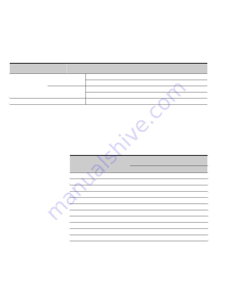
Table 3‐7. Power Cable Terminations for the Power Xpert 9395 Model 1085 or 1085HR Battery Cabinet
Terminal Function
Terminal
Function
Type
Terminations
Tightening Torque
Nm (lb in)
Size and Type of
Screw or Bolt Size
DC Input and Output
Battery
+
Positive
Pressure
2 - #2-600 kcmil
42.4 (375)
3/8
”
Hex
Bolt
2 - 1 Bolt Mounting
22.6 (200)
M10 Hex
Battery
Negative
Pressure
2 - #2-600 kcmil
42.4 (375)
3/8
”
Hex
Bolt
2 - 1 Bolt Mounting
22.6 (200)
M10 Hex
Ground
Ground
Ground
Pressure
2 - #14–1/0
5.6 (50)
7/16
”
Slot
NOTE
Customer ground, sized in accordance with NEC Table 250.122, can be run in any conduit listed. Refer to the appropriate UPS manual.
A battery disconnect switch is recommended, and may be required by NEC or local
codes when batteries are remotely located. The battery disconnect switch should be
installed between the battery and the UPS.
External DC input overcurrent protection and disconnect switch for the remote
battery location is to be provided by the user. Table 3‐8 lists the maximum rating for
continuous‐duty rated circuit breakers satisfying the criteria for both.
Table 3‐8. Recommended DC Circuit Breaker or Disconnect Ratings
UPS Model
Power Xpert 9395
Input Rating
Common Battery
Input Rating
Separate Battery
480V
480V
275/225
600A
600A
275/250
700A
700A
275/275
700A
700A
550/450
1200A
700A
550/500
1600A
700A
550/550
1600A
700A
825/650
2000A
700A
825/750
2000A
700A
825/825
2500A
700A
1100/1000
3000A
700A
1100/1100
3000A
700A


