135
9395P 250 kVA / 275 kVA / 300 kVA
User’s and Installation Guide
14.
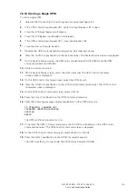
On the UPM 1 Control Command screen, select
UPM ON
.
15.
Press the
SELECT
pushbutton on the UPM 1 Command menu bar.
16.
Verify the following messages display sequentially on the UPM status line:
DC STARTING, CHARGER OFF
INVERTER STARTING
INVERTER
SYNCING
READY
The UPM 1 rectifier and inverter turn on.
If the Inherent Redundancy option is enabled, a loss of redundancy alarm will be issued.
Silence the alarm and continue to Step 17.
17.
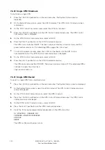
Repeat Steps 12 through 15 selecting
UPM 2
to start UPM 2.
18.
Verify the following messages display sequentially on the UPM status line:
DC STARTING, CHARGER OFF
INVERTER STARTING
INVERTER
SYNCING
READY
The UPM 2 rectifier and inverter turn on.
19.
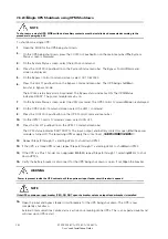
If the UPS is a three UPM model, repeat Steps 12 through 15 selecting
UPM 3
to start UPM 3.
20.
Verify the following messages display sequentially on the UPM status line:
DC STARTING, CHARGER OFF
INVERTER STARTING
INVERTER
SYNCING
READY
The UPM 3 rectifier and inverter turn on.
21.
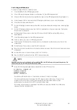
If the UPS is a Plus 1 model or an upgraded 825/550, repeat Steps 12 through 15 selecting
UPM 4
to start UPM 4.
22.
Verify the following messages display sequentially on the UPM status line:
DC STARTING, CHARGER OFF
INVERTER STARTING
INVERTER
SYNCING
READY
The UPM 4 rectifier and inverter turn on. When the inverter reaches full voltage, the UPS is
ready to transfer to the Online mode and supply the critical load.
23.
Repeat Steps 1 through 22 for each UPS in the distributed bypass system.
To transfer to Online mode after starting individual UPMs, follow the procedure in paragraph 7.6.18 .
NOTE
Summary of Contents for Power Xpert 9395P 250 kVA
Page 1: ...User s and Installation Guide Power Xpert 9395P UPS 250 kVA 275 kVA 300 kVA...
Page 2: ......
Page 3: ...Power Xpert 9395P UPS 250 kVA 275 kVA 300 kVA User s and Installation Guide...
Page 168: ......
Page 169: ......
Page 170: ...614 01919 00...

