Eaton
®
Power Xpert
®
9395P-600 (300V-600V) Installation and Operation Manual 164000710—Rev 07
113
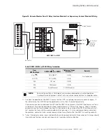
Table 38. Pull-Chain Wiring Terminations with MOBs
From
To
Function
UPS 1 CAN Bridge Card J3–1 (Alarm)
MOB 1 Aux 1 NC
MOB Open Alarm
UPS 1 CAN Bridge Card J3–2 (Alarm Return)
MOB 1 Aux 1 Com
UPS 1 TB2–1 (Pull Chain)
MOB 1 Aux 2 NO
Pull Chain
UPS 2 TB2–2 (Pull Chain Common)
UPS 2 TB2–2 (Pull Chain Common)
Pull Chain Common
UPS 2 CAN Bridge Card J3–1 (Alarm)
MOB 2 Aux 1 NC
MOB Open Alarm
UPS 2 CAN Bridge Card J3–2 (Alarm Return)
MOB 2 Aux 1 Com
UPS 2 TB2–1 (Pull Chain)
MOB 2 Aux 2 NO
Pull Chain
UPS 2 TB2–2 (Pull Chain Common)
UPS 3 TB2–2 (Pull Chain Common)
Pull Chain Common
UPS 3 CAN Bridge Card J3–1 (Alarm)
MOB 3 Aux 1 NC
MOB Open Alarm
UPS 3 CAN Bridge Card J3–2 (Alarm Return)
MOB 3 Aux 1 Com
UPS 3 TB2–1 (Pull Chain)
MOB 3 Aux 2 NO
Pull Chain
UPS 3 TB2–2 (Pull Chain Common)
UPS 4 TB2–2 (Pull Chain Common)
Pull Chain Common
UPS 4 CAN Bridge Card J3–1 (Alarm)
MOB 4 Aux 1 NC
MOB Open Alarm
UPS 4 CAN Bridge Card J3–2 (Alarm Return)
MOB 4 Aux 1 Com
UPS 4 TB2–1 (Pull Chain)
MOB 4 Aux 2 NO
Pull Chain
MOB 1 Aux 2 Com
MOB 2 Aux 2 Com
Pull Chain MOB Common
MOB 2 Aux 2 Com
MOB 3 Aux 2 Com
MOB 3 Aux 2 Com
MOB 4 Aux 2 Com
55..33
IInnssttaalllliinngg aann O
Oppttiioonnaall R
Reem
moottee M
Moonniittoorr P
Paanneell IIII
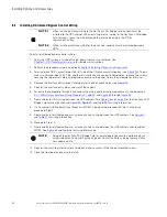
To install RMP II wiring:
1.
Verify the UPS system is turned off and all power sources are removed. See
for shutdown instructions.
2.
Perform the procedure listed in paragraph
Installing an Optional Hot Sync CAN Bridge Card
.
NOTE
If mounting to a hollow wall, secure the enclosure to a wood or metal stud within the
wall. Do not use hollow wall anchors.
3.
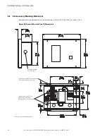
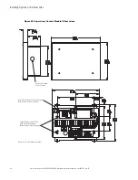
Securely mount the RMP II at the desired location. See
for mounting hole locations.
NOTE
When installing signal wiring for CAN card J3 terminals, conduit must be installed
between the device and the UPS cabinet.
Summary of Contents for Power Xpert 9395P-600/600
Page 8: ......
Page 226: ...16400071007 164000710 07...


