UPS System Installation
Eaton
®
Power Xpert
®
9395P-900 UPS Installation and Operation Manual P-164000501—Rev 09
www.eaton.com/powerquality
4-29
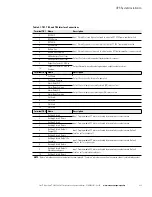
Table 4-1. TB1, TB2, and TB3 Interface Connections
Terminal TB1
Name
Description
1
REPO NC
Input: Normally-closed dry contact used to activate UPS EPO from a remote switch.
2
REPO Return
3
REPO NO
Input: Normally-open dry contact used to activate UPS EPO from a remote switch.
4
REPO Return
5
Battery Aux
Input: Normally-open contact used to indicate when UPS battery breaker is open or closed
6
Battery Aux Common
7
48 Vdc Battery Shunt Trip +
Output: Contacts used to open battery breaker or disconnect.
8
48 Vdc Battery Shunt Trip
–
9
Output Contactor K3 NC Aux
Output: Normally-closed contact opens when output contactor closes.
10
Output Contactor K3 NC Aux
Common
Terminal TB2
Name
Description
1
Pull Chain
Output: Backup control for parallel operation.
2
Pull Chain Common
3
Alarm Relay NC
Output: General purpose normally-closed (NC) relay contact.
4
Alarm Relay Common
5
Alarm Relay NO
Output: General purpose normally-open (NO) relay contact.
6
Alarm Relay Common
7
Not Used
8
Not Used
9
Not Used
10
Not Used
Terminal TB3
Name
Description
1
Building Alarm 1
Input: Programmable UPS alarm, activated by a remote dry contact closure.
2
Building Alarm 1 Return
3
Building Alarm 2
Input: Programmable UPS alarm, activated by a remote dry contact closure.
4
Building Alarm 2 Return
5
Building Alarm 3 Default:
Charger Off
Input: Programmable UPS alarm, activated by a remote dry contact closure. Default
function set for charger off.
6
Building Alarm 3 Return
7
Building Alarm 4 Default: On
Generator
Input: Programmable UPS alarm, activated by a remote dry contact closure. Default
function set for on generator.
8
Building Alarm 4 Return
9
Building Alarm 5 Default:
Maintenance Bypass
Input: Programmable UPS alarm, activated by a remote dry contact closure. Default
function set for maintenance bypass.
10
Building Alarm 5 Return
NOTE
“Return“ indicates connection to electronics circuit ground. “Common” indicates connection to common side of isolated relay contact.
Summary of Contents for Power Xpert 9395P-900 Series
Page 2: ......
Page 8: ...This page intentionally left blank...
Page 33: ...Section I Installation...
Page 34: ......
Page 139: ...Section II Operation...
Page 140: ......
Page 231: ......
Page 232: ...P 164000501 6 P 164000501 9...


