background image

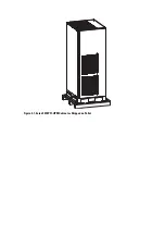
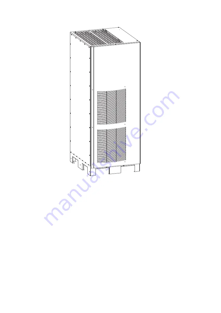
Figure 1-1. Eaton 9395P Field Installed UPM

1.3 Symbols, controls, and indicators

The following are examples of symbols used on the UPS or accessories to alert you to important 
information:

Summary of Contents for Power Xpert 9395P

Page 1: ...Mechanical Installation Manual Power Xpert 9395P Field Installed UPM P 16400478...

Page 2: ......

Page 3: ...Power Xpert 9395P Field Installed UPM Mechanical Installation Manual...

Page 4: ...tenance des batteries et de l onduleur Veuillez consulter enti rement ces instructions avant de faire fonctionner l quipement et conserver ce manuel afin de pouvoir vous y reporter ult rieurement WARN...

Page 5: ...tion Plan and Unpacking 7 3 1 Creating an Installation Plan 7 3 2 Preparing the Site 7 3 3 Inspecting and Unpacking the FI UPM Cabinet 11 4 Field Installed UPM Installation 15 4 1 Preliminary Installa...

Page 6: ......

Page 7: ...e 3 4 FI UPM Cabinet Dimensions Bottom View dimensions are in millimeters inches 10 Figure 3 5 FI UPM Cabinet Dimensions Bottom View with Mounting Brackets dimensions are in millimeters inches 10 Figu...

Page 8: ......

Page 9: ...t of the sales contract for the FI UPM Contact an Eaton service representative in advance usually a two week notice is required to request service 1 1 Using This Manual This manual describes how to me...

Page 10: ...Figure 1 1 Eaton 9395P Field Installed UPM 1 3 Symbols controls and indicators The following are examples of symbols used on the UPS or accessories to alert you to important information...

Page 11: ...bilities of the UPS system Visit www eaton com power quality or contact Eaton service representative for information on how to obtain copies of these manuals 1 5 Getting Help If help is needed with an...

Page 12: ...Regional locations and telephone numbers A question about any of the information in this manual A question this manual does not answer Please call your local service representative...

Page 13: ...nected from an AC source To reduce the risk of fire or electric shock install this UPS and FI UPM in a temperature and humidity controlled indoor environment free of conductive contaminants Ambient te...

Page 14: ...6...

Page 15: ...applies to the system being installed Use the procedures and illustrations in Section 3 2 and Chapter 4 to create a logical plan for installing the system 3 2 Preparing the Site For the FI UPM to ope...

Page 16: ...erating Range 20 25 C Maximum Relative Humidity 95 noncondensing The FI UPM ventilation requirements are shown in Table 3 3 Table 3 3 FI UPM Air Conditioning or Ventilation Requirements During Full Lo...

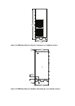
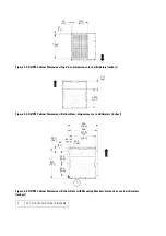
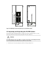
Page 17: ...net Dimensions Front View dimensions are in millimeters inches Figure 3 2 FI UPM Cabinet Dimensions Right Side View dimensions are in millimeters inches 1871 5 73 7 732 28 8 871 34 3 831 5 32 7 39 5 1...

Page 18: ...ttom View dimensions are in millimeters inches Figure 3 5 FI UPM Cabinet Dimensions Bottom View with Mounting Brackets dimensions are in millimeters inches 1 12 7 0 5 X 15 8 0 62 Slot 6X 758 8 20 37 1...

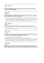
Page 19: ...bolted to a wooden pallet and protected with outer protective packaging material see Figure 3 7 WARNING The FI UPM cabinet is heavy see Table 3 1 on page 8 If unpacking and unloading instructions are...

Page 20: ...cal or the cabinet may tip over 3 Set the pallet on a firm level surface allowing a minimum clearance of 3m 10 ft on each side for removing the cabinet from the pallet NOTE The FI UPM cabinet is shipp...

Page 21: ...Figure 3 7 Eaton 9395P FI UPM Cabinet as Shipped on Pallet...

Page 22: ......

Page 23: ...tallation is complete However remove the shield before operating the UPS system Once the debris shield is removed do not place objects on the ventilation grill A FI UPM is always designated as UPM 4 4...

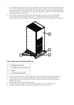
Page 24: ...side shipping bracket If installing the cabinet permanently retain the shipping bracket and securing hardware for later use Figure 4 1 Removing the Left Side Shipping Bracket 3 Remove the three bolts...

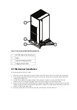
Page 25: ...d inside of the cabinet Locate the nylon grommet from the hardware kit If not already installed install the nylon grommet in the knockout hole 4 Using a forklift move the FI UPM cabinet to the final i...

Page 26: ...ll the FI UPM front panel removed in Step 6 and secure with the retained hardware 9 If permanently mounting the system proceed to Step 10 otherwise continue to Step 12 10 Using the retained hardware r...

Page 27: ...advance usually a two week notice is required to reserve a preferred startup date 4 6 Completing the Installation Checklist The final step in installing the FI UPM is completing the following Installa...

Page 28: ......

Page 29: ...nstalled and operating correctly The area around the installed UPS system is clean and dust free It is recommended that the UPS be installed on a level floor suitable for computer or electronic equipm...

Page 30: ...Notes...

Page 31: ...lternation or ambient conditions of the equipment do not fulfil the requirements specified in the documentation delivered with the unit and other relevant documentation Equipment subjected to misuse n...

Reviews: