Eaton Power Xpert Gateway PXGX PDP Card User’s Guide 164202122—Rev 1
55
Chapter 7
Modbus Registers
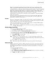
This chapter describes how to address each of the following PDPs using Modbus TCP/IP:
l
Power Distribution Unit (PDU)
l
Remote Monitor Panel (RPP)
l
Rack Power Module (RPM)
l
Energy Management System Upgrade Kit (EMS-UGK)
l
Power Distribution Rack (PDR)
l
Or a specific panel in a PDU, RPP, RPM, EMS-UGK, or PDR, and a specific breaker in a panel
Note:
To obtain the panel or circuit breaker data, the PDP must have the Energy Management System
(EMS) Level 3 option installed.
A PDP distributes power through one or more circuit breaker panels. Each panel consists of several circuit
breakers. Each circuit breaker contains more than 30 parameters, such as voltage, current, power, and alarms.
The value of each parameter is stored in a corresponding Modbus data register.
Because there are many panels in a PDP, it is necessary to identify a specific breaker and specify the panel
containing that breaker. It is likely that Breaker #5 in Panel #1 has different data than Breaker #5 in Panel #7.
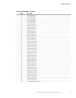
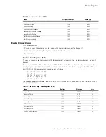
The tables in this chapter list sample names of the PDP parameters and their corresponding Modbus registers
for:
l
PDP summary data
l
Panel summary data
l
Breaker data
The values of the parameters can be read over an Ethernet network by using Modbus TCP/IP building
managemnt programs or Modbus TCP/IP analyzer programs.
Note:
Some Modbus programs provide an option for zero- or one-based addressing. Select the option for
zero-based addressing. The Modbus numbering scheme for the PDP starts at 0, so physical coil
number 1 corresponds to Modbus register number 0, coil number 2 corresponds to Modbus register
number 1, and so on.
Note:
If your Modbus program requires one-based addressing, add a one to the register addresses listed in
Table 7 on page 61. For example, one-based addressing for the vendor name would be 1033
(1032 + 1).


