6
2. Trip unit description
Power XPert® release triP unit for MagnuM PXr circuit breakers
MN013015EN January 2022 www.eaton.com
There are three buttons below the display (see Figure 3) that
are used to control what information is shown on the display
and to select certain configuration options.
Figure 3. Typical display navigation.
•
The Up arrow button
is used to move up in the
menu display screen or increase an adjustment value.
•
The Down arrow button
is used to move down in
the menu display screens or decrease an adjustment
value.
•
The Enter button
is used to enter the menu or
setting and can also go back the previous menu.
2.3 Cause-of-Trip indicators
All PXR family trip units record the Cause-of-Trip (CoT) in
memory. The CoT is shown on LEDs on the front of the
trip unit and is available through PXPM and communications
interfaces. The four CoT indicators on the face of the trip
unit are labeled: LONG, SHORT, INST, and GND.
The appropriate CoT indicator blinks when a current level
pickup setting is exceeded. After a trip event, the indicator
blinks (one second on, three seconds off) and the cause will
be shown on the display if auxiliary power is applied. The
indicators and the display can be cleared by pressing the
RESET button.
•
LONG – Long delay trip or over- temperature trip has
occurred.
•
SHORT – Short delay trip or an abnormal breaker condi-
tion has occurred.
•
INST
– Instantaneous, making current release, over-
ride, or maintenance mode trip.
•
GND
– Ground trip or ground alarm condition has
occurred.
2.4 PXR 20 – Configure using rotary switches
In the PXR 20, there are between five and eight rotary
switches which configure the core protection settings. Each
switch has ten positions and is set to achieve the appropriate
trip curve response. Each switch can be set using a small
screwdriver.
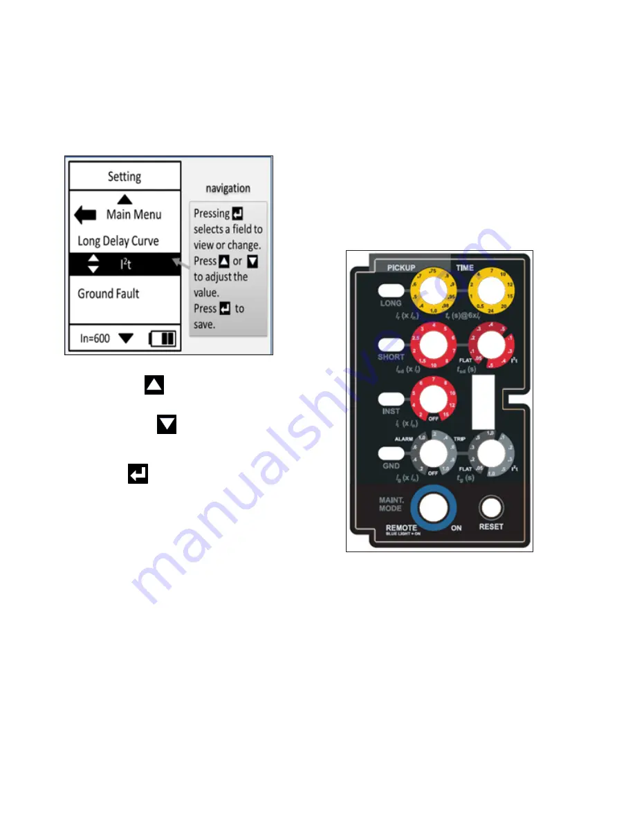
Figure 4. PXR 20 switch settings.
The rotary switches have legends above (PICKUP, TIME) and
to the left (LONG, SHORT, INST, GND and MAINT. MODE)
which indicate their use. For each rotary switch, there is a
color-coded ring: yellow for long (L) settings, red for short
(S) and instantaneous (I) settings, and grey for ground (G)
settings. The legend within the ring and arrow on the switch
indicate the value for each position. The formula that relates
the setting to breaker ratings is below left of each switch.
At the bottom, the switch with the blue ring is used for
enabling Maintenance Mode on trip units with the Arc Flash
Reduction Maintenance System™ (ARMS). The blue ring
illuminates when the trip unit is in Maintenance Mode.


