10
3. Protection functions
Power XPert® release triP unit for MagnuM PXr circuit breakers
MN013015EN January 2022 www.eaton.com
3. Protection functions
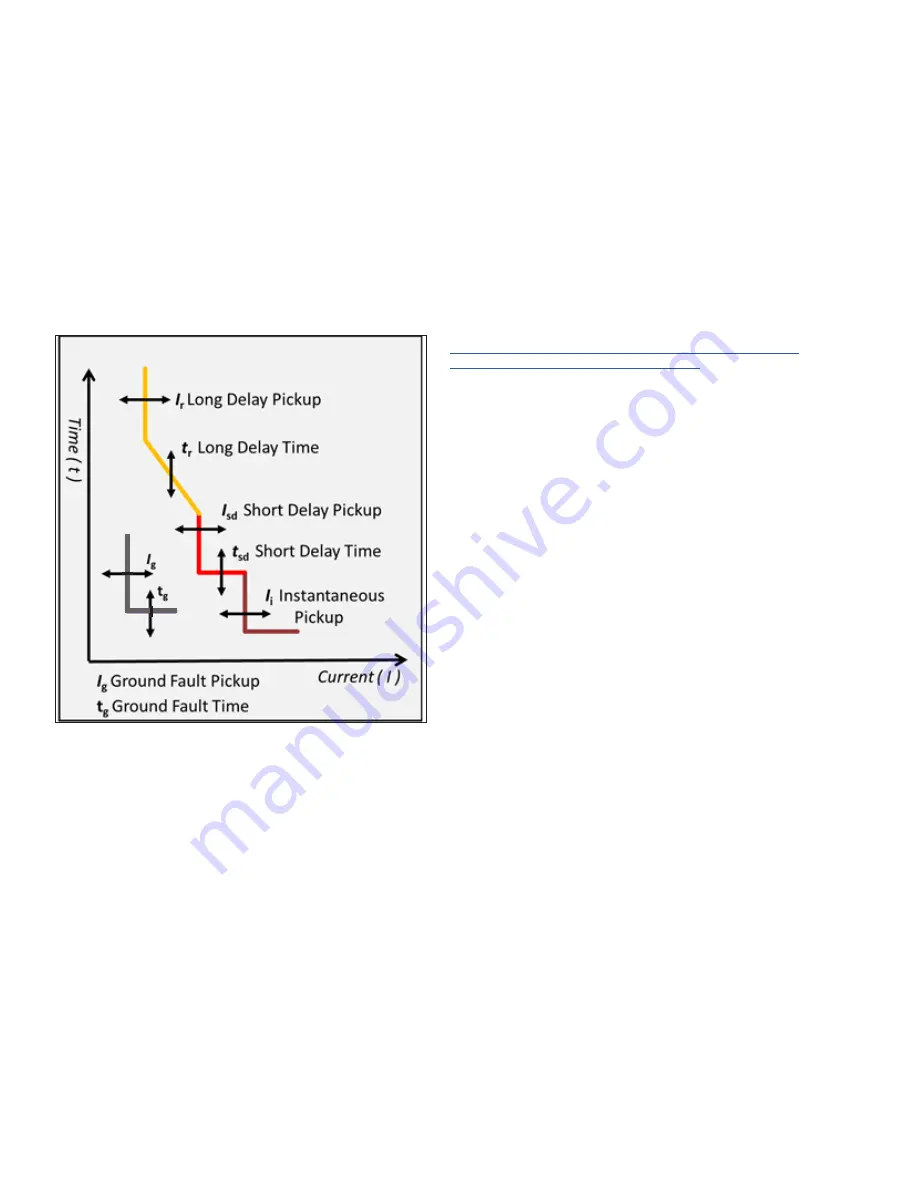
The PXR trip unit protection settings are designed to be
easily customized to any application. Settings for long delay
pickup, long delay time, short delay pickup, short delay time,
instantaneous pickup, ground fault pickup, and ground fault
time are all independently configurable. These functions
are set using the Power Xpert Protection Manager (PXPM)
software, using the display and navigation buttons, or rotary
switches on the front of the trip unit.
Figure 8. Settings and trip curve.
Before placing any circuit breaker in operation, set each trip
unit protection setting to the values specified by the engi-
neer responsible for the installation.
3.1 Password security
Protecting your system from cybersecurity threats is very
important. PXR trip units have four-digit passwords used to
secure settings and to enable secondary injection testing. To
change a setting, which is not set by a physical switch, will
require you to enter the password. Authorization to make
changes will timeout after ten seconds of inactivity. If three
attempts are made with an incorrect password, all access
will be denied for ten minutes.
Two levels of password are available: Admin and User. The
factory default is the Admin level and the password is ‘0 0
0 0’. The Admin can, if desired, create a user and decide if
the User can change protection setpoints or not. Password
security is enforced when using the display, PXPM software,
and when another device attempts a change via a commu-
nication network. Passwords should only made available to
those individuals who require it.
Changing the factory default password when the PXR is
installed or commissioned is a key element of a comprehen-
sive cybersecurity policy. Passwords are four-digits long,
numeric characters 0 to 9. When entering, the numbers will
not be shown on the display. Instead, an asterisk (*) will be
shown to protect the security of your password.
For additional information about best practices, please review
Cybersecurity Considerations for Electrical Distribution
Systems (WP152002EN):
http://www.eaton.com/ecm/groups/public/@pub/@eaton/@
corp/documents/content/pct_1603172.pdf
3.2 Overload/long delay settings
The PXR trip unit offers a wide range of settings for overload
protection. Long delay pickup (LDPU or Ir) setting ranges
from 0.4 to 1.0 and is expressed as a multiple of the frame’s
current rating (I
n
). I
r
is also the basis for the short delay
current setting. The tolerance for long delay pickup is 105%
to 115% of the setting to ensure that the circuit breaker can
carry the full rating of (I
r
), without tripping.
The long delay time (t
r
) settings range from 0.5 to 24
seconds. They represent the total clearing times when
the current value equals six times (I
r
) when an I
2
t slope
is selected. All times are referenced from the top of the
tolerance band, ensuring that the time never exceeds that
maximum setting. For the other slopes, please refer to the
trip curves for total clearing time.
The I
2
t setting is the factory default curve for long delay.
PXR 25 allows the curve to be changed to alternative
curves to better match the requirements for protection and
coordination.
•
I
2
t
Inverse time current curve, standard distribution
protection (factory default);
•
I
4
t
Extremely inverse time current curve, coordination
with fuses or special types of loads;
•
I
1/2
t Moderately inverse time curve; or
•
I
1
t
Slightly inverse time curve.
If a long delay causes the circuit breaker to trip, the LONG
indicator will be illuminated and the long delay message will
be displayed.
3.2.1 Long delay thermal memory
In addition to the standard long delay protection, a long
thermal memory (LTM) function is supported. This protects
load circuits from the effects of repeated overload condi-
tions. LTM is enabled or disabled using the display and navi-
gation buttons or using the Power Xpert Protection Manager
software.
As an example, if a circuit breaker is closed soon after a
long delay trip, and the current again exceeds the long delay
setting (I
r
), the LTM automatically reduces the time to trip
to allow for the fact that the load conductor temperature is


