19
4. Complementary features
Power XPert® release triP unit for MagnuM PXr circuit breakers
MN013015EN January 2022 www.eaton.com
PXPM can also be used by navigating: Setpoint Configuration
-> Connect to Unit -> Expand the System Settings bar ->
Relay Function Configuration select “Other” and “Open
Breaker Pulse”.
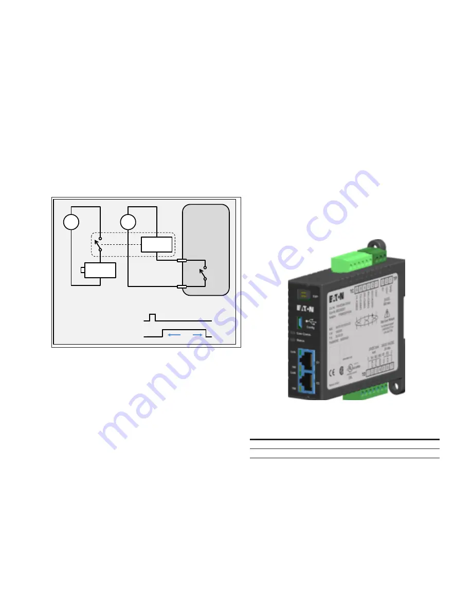
Wire the chosen on-board relay to complete a circuit to
the SR. The on-board relay should energize the coil of an
interposing relay using control power. The on-board relay
contacts are not designed to switch high current induc-
tive loads. The wiring terminals and relay specifications
are found in Section 4.6 - Secondary wiring terminals for
Magnum PXR. The interposing relay contacts should be
chosen which matches your ST specifications and the power
source used to energize the ST.
Figure 15. Typical wiring to open/close.
The Modbus client is then programmed to send a remote
control command to the trip unit. The command and its
complement are written to three consecutive registers.
This triggers the trip unit to close the on-board relay for
two seconds which has been mapped to the open breaker
pulsed function. In turn, this energizes the ST and opens
the breaker. See Section 9.5 - Remote control commands for
details of the command encoding.
To close the breaker, substitute Close for Open and spring
release (SR) for shunt trip (ST). You may want to include a
motor-operator accessory in the circuit breaker to charge the
closing springs for fully remote operation.
4.3 Integrated Modbus RTU
A Modbus communication port is integrated into the PXR trip
unit for certain styles. Modbus is a communication protocol
used for transmitting information between devices. The PXR
is a responding device, using the remote terminal unit (RTU)
protocol, it will process commands from another device and
respond with the function or data requested. Breaker status
(closed/tripped/open), setpoints, and operating information
are all available via Modbus.
The trip unit supports Modbus function codes 2, 3, 4, 6, and
16. Single and multiple read or write operations can transact
up to 122 registers (244 bytes) in a single Modbus message.
The factory default configuration is device address = 1,
baud rate = 9600, parity = even, stop-bits = one.
The physical layer is based on 3-wire RS-485 and connects at
the circuit breaker’s secondary terminals labeled MBA, MBB,
and MBG. See Section 4.6 - Secondary wiring terminals
for Magnum PXR for details on the connector locations and
recommended cable.
The detailed Modbus register map including network config-
uration options is shown in Section 9 - Modbus register map.
4.4 Communications adapter modules (CAMs)
All styles of the Magnum PXR trip unit support communica-
tion adapter modules (CAMs). These modules provide
communication to either Ethernet or Profibus field networks.
Figure 16. ECAM module.
Table 9. Available CAM modules.
network
Module
instruction leaflet
Ethernet (Modbus TCP)
PXR-ECAM-MTCP
IL0131132EN
Profibus DP
PXR-PCAM
IL120009EN
These modules are remotely mounted on a DIN rail and field-
wired into the trip unit using the circuit breaker’s secondary
terminal block. The field bus is then wired to a connection
on the CAM module. See Section 4.6 - Secondary wiring
terminals for Magnum PXR for details.
Please consult the respective Instruction leaflets for details
of each CAMs functionality and configuration.
Typical wiring for Open / Close via Modbus using ST/SR
Circuit
breaker
Use one of the
on-board
relay outputs
V
RYC
RYx
Interposing
relay coil
Shunt trip
coil
V
Modbus close
command
On-board relay
contact
2 s


