14
3. Protection functions
Power XPert® release triP unit for MagnuM PXr circuit breakers
MN013015EN January 2022 www.eaton.com
3.7.5 Phase loss
Phase loss protection is used for complete loss of one or
two phases. If the difference between the maximum and
minimum of any of the three phase currents is greater than
75%, for the time delay, then the protection action will be
taken. Action will be taken only when at least one phase
current is greater than 50% of the Long Delay Pickup (LDPU
or I
r
) setting.
3.7.6 Reverse power
Power flowing through the breaker is continuously moni-
tored. If the reverse real power is greater than the pickup
for the time delay, then the action will be taken.
3.8 Maintenance mode
The PXR trip units support Eaton’s Arc Flash Reduction
Maintenance System
TM
(ARMS), also known as maintenance
mode. When active, the trip unit will trip the breaker with
no intentional delay whenever the configured pickup level is
exceeded. The maintenance mode function operates regard-
less of the instantaneous settings. If maintenance mode
causes the circuit breaker to trip, the INST indicator will be
illuminated and the maintenance mode trip message will be
displayed.
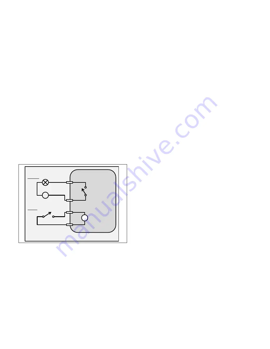
Figure 11. Typical maintenance mode wiring.
The maintenance mode pickup level setting is configured
using the display and navigation buttons or PXPM software.
They range from 1.5 (most protective) to 10, expressed as
a multiplier of I
n
. The adjustable current settings allow for
different levels of protection. A higher level may be needed
when, for example, another load fed from this breaker may
contain motors that are being started and create large inrush
currents over the lowest trip current level. The selection
of one of the reduction settings should be determined and
selected by a person who is experienced in power system
analysis.
3.8.1 Activation and indication of maintenance mode
A blue colored ring surrounding the MAINT. MODE switch on
the front of the trip unit always illuminates to confirm when
the function is active. Additionally, a relay can be mapped
which will close to indicate when maintenance mode is
active.
When the switch on the front of the trip unit is in the ON
position, maintenance mode is active and cannot be turned
off remotely.
When the switch is in the REMOTE position, maintenance
mode can be remotely activated:
•
By a contact wired to the secondary terminal block of
the breaker’s MM terminal. See Section 4.6 - Secondary
Wiring Terminals for wiring information and contact
requirements.
•
Via communications. This can be done through the
Modbus register map. See Section 9 - Modbus register
map for details.
•
Using PXPM software connected to the trip unit via USB.
Maintenance mode will be active when any of the methods
is calling for activation. If you have enabled maintenance
mode using multiple methods, to disable it requires remov-
ing each of those methods.
Typical maintenance mode wiring
Circuit breaker
L
Maintenance
mode enable
Use one of the
general-purpose
relay outputs
V
Field supplied contact to
enable maintenance mode
Field supplied light to
indicate maintenance mode
V
MM
V0
RYC
RYx


