8
2 PXR user interface
PXR tRiP units foR PoweR Defense molDeD case ciRcuit bReakeRs
MN012007EN March 2019 www.eaton.com
For additional information and cyber security best practices, please go to www.eaton.com/
cybersecurity. Detailed guidance is under the “Documentation” tab on this cybersecurity
home page.
2.1.11 Catalog number and I
n
rating
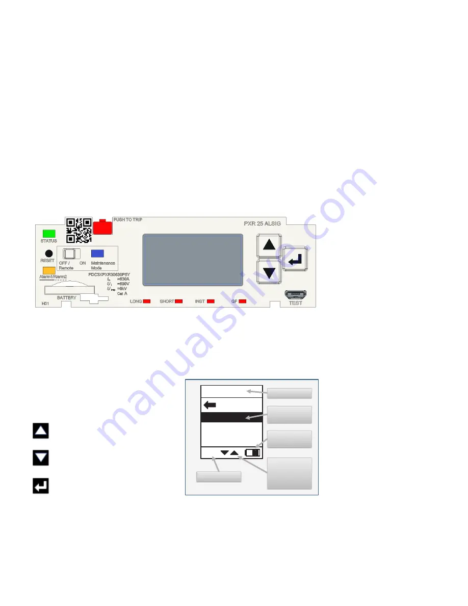
Trip unit family and protection functionality are printed in the upper right of the front panel.
The rated I
n
values are printed near the test port. The catalog number is also printed on the
front, it starts with “PD” and the last three digits define the factory configuration options.
See Section 10.1: Identifying the trip unit for a full list of options.
2.1.12 QR code
The 2D barcode (QR code) on the front of each trip unit encodes the trip unit catalog and
serial number. This can be used to look-up product information that is available on-line from
Eaton.
2.2 PXR 25, PXR 25 Motor Protection, and 20D display with keypad
The PXR 20D and PXR 25 user interface (UI) has a display and keypad on the front of the trip
unit. This display provides information regarding the operation of the trip unit and the
method to select configuration options. The keypad provides for navigation through the
menu structures. Information is presented on the display in English, Chinese, German,
Spanish, or up to two additional languages (loaded by PXPM). To provide for easier reading
of the display with the circuit breaker mounted on its side, the display is configurable to
rotate 90 degrees left or right.
There are three navigation buttons near the
display used to control the information shown
on the display and to select configuration
options:
Up arrow button
- Used to move up in
the menu display screen or increase an
adjustment value.
Down arrow button
- Used to move
down in the menu screens or decrease
an adjustment value.
Enter button
- Used to enter a menu or
configuration setting or to go back to the
previsions menu.
Each trip unit style has configurable settings for protection and other features. They can
be configured using either the front panel or by using PXPM software. Details regarding
the available protection settings for each frame are found in Section 9: Available protection
settings.
PXR 25, PXR 25 Motor Protection, and 20 D display with keypad
Main Menu
Events
Trip
Alarm
ZSI
Summary
Example of a
highlighted field
Battery life
indicator
Indicates menu
fields above or
below the
highlighted field
ZSI indicator
Menu title
Events


