15
3 Line protection setting description
PXR tRiP units foR PoweR Defense molDeD case ciRcuit bReakeRs
MN012007EN March 2019 www.eaton.com
Protection Function: Reverse Power
Power flowing through the breaker is continuously monitored. If the reverse real power is
greater than the pickup for the specified time delay, then the protection action will be taken.
3.6 Maintenance Mode protection (ARMS)
The PXR trip units support Eaton’s Arc Flash Reduction Maintenance System (ARMS), also
known as Maintenance Mode. When maintenance is being performed and the ARMS is
enabled, the trip unit will trip the breaker with no intentional delay whenever the configured
pickup level is exceeded. The Maintenance Mode protection overlays the LSI protection
functions and operates in parallel. If Maintenance Mode causes the circuit breaker to trip,
the “INST” indicator will be illuminated and the “Maintenance Mode Trip” message will be
displayed if the style of trip unit has a display.
The Maintenance Mode pickup level setting is configured using the UI or PXPM software.
They range from 2.5 (most protective) to 10, expressed as a multiplier of In. The adjustable
current settings allow for different levels of protection. A higher level may be needed when,
for example, another load fed from the ARMS protected breaker may contain motors that
are being started and create large inrush currents over the lowest trip current level. The
selection of one of the reduction settings should be determined and selected by a person
who is experienced in power system analysis.
3.6.1 Actuating and indicating Maintenance Mode protection
There are three ways to actuate the Maintenance Mode function, locally, remotely using a
contact, or remotely using communications. A blue LED on the trip unit always illuminates
to confirm when the function is enabled.
•
For locally actuating the Maintenance Mode function, use the slide switch on the front
of the trip unit. When in the “ON” position, Maintenance Mode is enabled locally and
cannot be turned-off remotely or by communications. This method does not require auxil-
iary power to the trip unit, and the blue LED on the face of trip unit will light when the trip
unit is self-powered.
•
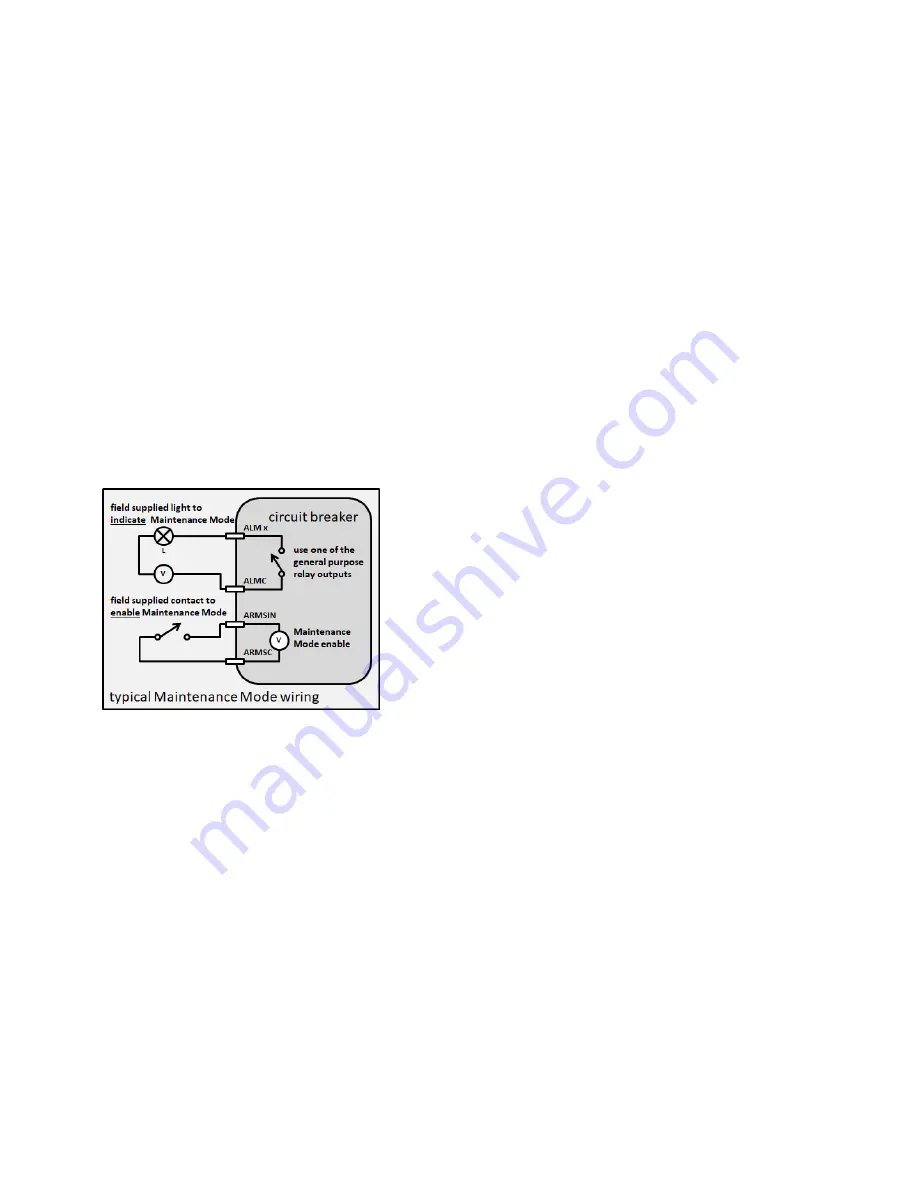
Maintenance Mode can be remotely actuated by an external contact wired to the breaker
when the local switch is in the “OFF/Remote” position. See Section 5.1: Wiring table
for details regarding the contact and wiring length. When Maintenance Mode is enabled
by an external contact, it must also be disabled via the external contact. Moving the
local switch from “OFF/Remote” to “ON” and back to “OFF/Remote” will not disable
Maintenance Mode. Auxiliary power (24 V DC) is required for Maintenance Mode remote
activation
•
A third method to actuate Maintenance Mode is via communications. This can be done
through a modbus register, a communications adapter module (CAM) or by the configura-
tion software using the USB port. When Maintenance Mode is enabled by communica-
tions, it must also be disabled via communications. Moving the local switch from “OFF/
Remote” to “ON” and back to “OFF/Remote” will not disable Maintenance Mode.
Auxiliary power (24 V DC) is required for communications functionality, including mainte-
nance mode remote activation.


