17
4 Communication functionality
PXR tRiP units foR PoweR Defense molDeD case ciRcuit bReakeRs
MN012007EN March 2019 www.eaton.com
ZSI in the PXR trip unit is fully compatible with ZSI in the Digitrip for Magnum, Digitrip for
NRX, OPTIM and 310+ Series C and Series G trip units. If a PXR trip unit has the ZSI option
but it is not needed in an application, it may be disabled using the Power Xpert Protection
Manager software or the menus on the UI, or the Zout and Zin may be connected to “self-
interlock” the unit.
PXR trip units with a display have a visual indication of the ZSI system being active and
connected to the other breakers in the ZSI system. A small check-mark will appear next to
the ZSI when the trip unit receives a ZSI-IN signal. The general-purpose, configurable, relay
contacts may also be programmed to indicate ZSI signals and status.
3.9 Operating temperature
All models of trip units are designed for commercial/industrial circuit breaker environments.
The frames are rated for load and temperature per individual circuit breaker. As an additional
protection, if temperatures in the PXR trip-unit exceed 105 °C (220 °F), a factory-set over-
temperature protection feature will trip the circuit breaker to protect the internal electronic
components.
4 Communication functionality
The PXR family of trip units offers wide support for communications. A USB port is present
on all PXR family trip units. All PXR 20, 20D and 25 support external communication adapter
modules (CAM) while certain models have built-in Modbus-RTU.
4.1 Integrated Modbus - remote terminal unit (RTU)
A Modbus communication port is integrated into the PXR trip unit for certain styles. Breaker
status (closed/tripped/open), set points and operating information are all available via
Modbus. The trip unit responds to messages from the master using the remote terminal
unit (RTU) protocol. Modbus port configuration can be viewed and set using the user
interface (UI) or using Power Xpert Protection Manager software. The trip unit uses Modbus
function codes 02, 03, 04, 06, 08, and 16 and supports up to 122 registers (244 bytes) in a
single Modbus transaction.
The detailed Modbus register map is shown in Section 10: Modbus communication port
register map. Auxiliary power (24 V DC) is required for integrated Modbus communications
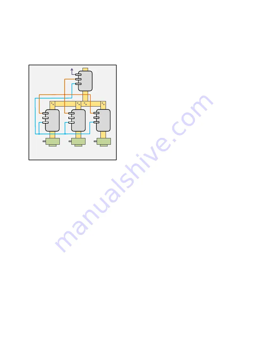
Zone Selective Interlock - showing Zin on
the Motor Protection Breakers not used
MP
breaker
ZOUT
ZIN
ZCOM
breaker
ZOUT
ZIN
ZCOM
MP
breaker
ZOUT
ZIN
ZCOM
MP
breaker
ZOUT
ZIN
ZCOM
motor
motor
motor
With a motor


