INSTALLATION
Eaton 5125 Tower UPS (1000–2200 VA) User's Guide
S
05147304 Rev C
www.eaton.com/powerquality
22
Installing the UPS
NOTE
Do not make unauthorized changes to the UPS or accessories; otherwise, damage
may occur to your equipment and void your warranty.
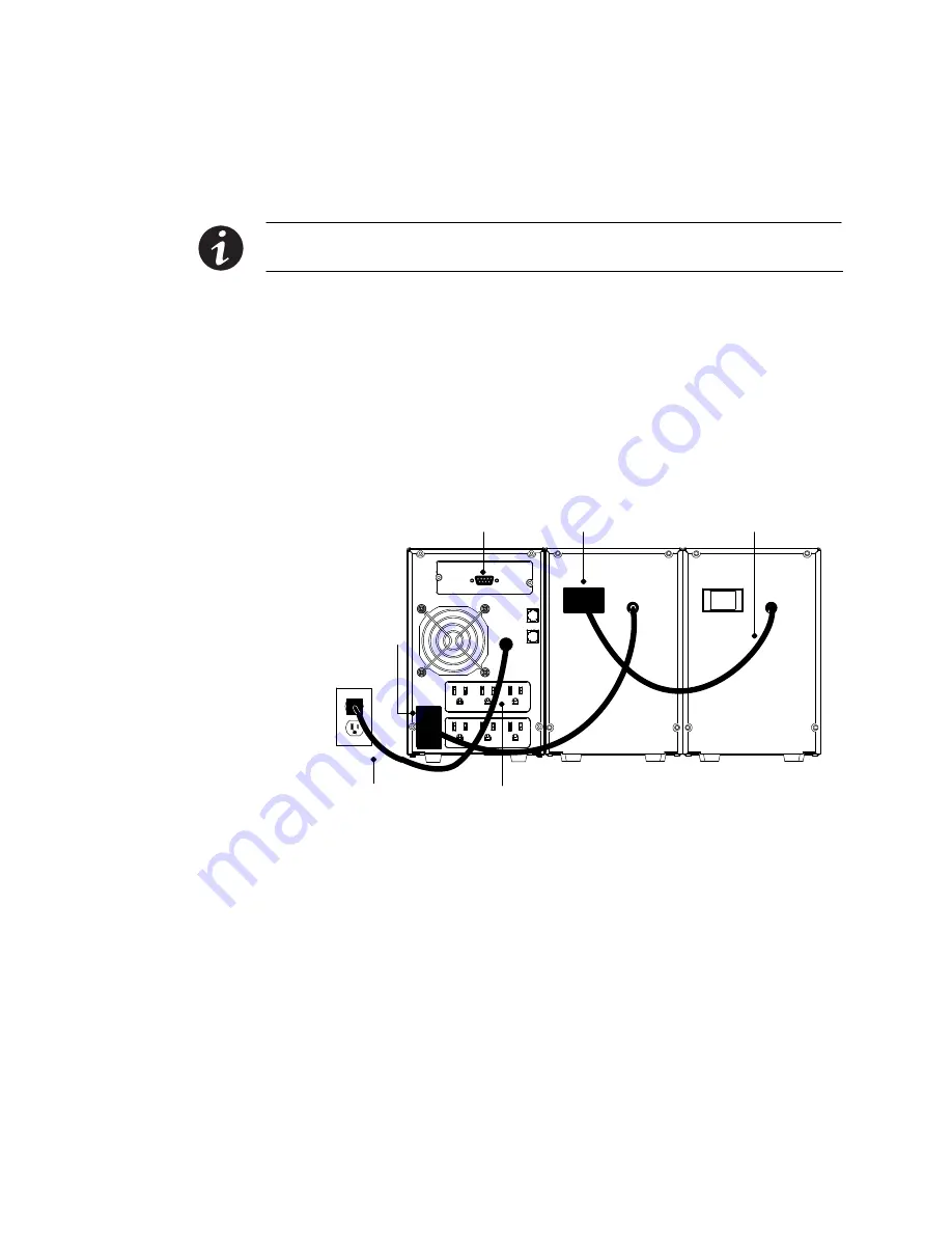
Figure 6 shows a typical installation only. See “UPS Rear Panels” on
page 24 for the rear panel of each model.
To install the UPS and optional Extended Battery Modules (EBMs):
1.
If installing an optional EBM, continue to Step 2; otherwise,
proceed to Step 3.
2.
Plug the EBM cable(s) into the battery connector(s) as shown in
Figure 6. Up to four EBMs may be connected to the UPS.
UPS Battery
Connector
EBM Cable
EBM Battery Connector
Output Receptacles
Communication Port
Power Cord
UPS
EBM
EBM
Figure 6. Typical UPS Installation with Two EBMs
3.
If you plan to install power management software, connect your
computer to the UPS communication port using the supplied
communication cable. For more information about communication
options, see page 35.


