background image

11

Table 1. Configuration Mode Parameters (cont.)

Parameter

LCD Message

Description

Default Settings

Manual Battery Test

Manual Bat Test

To initiate a manual battery test, press the 

button Battery 

Test

twice when “Manual Battery Test” is displayed on the
LCD.  During the test the LCD displays ON BATTERY.
The UPS resets the automatic timer after a manual
battery test. The LCD displays “Battery not charged”
when UPS test is requested but the battery is not
fully charged.

Manual UPS Test

Manual UPS Test

To initiate a manual UPS self-test, press the 

button

UPS Test

twice. During the test, the LCD displays ON BATTERY.

Site Wiring Fault Alarm

Site Fault Set

Select Enable or Disable. When enabled, the alarm sounds  Detect Enable
when the ground connection is missing or the line and 
neutral wires are reversed in the wall outlet.

Modem Support

Modem Support

This parameter is reserved for future use, and should not 

No Modem Support

be modified by the user.

Number of Extended 

Bat Pack Num Set

Select the number of EBMs connected to the UPS:

Extern Pack: 0

Battery Modules

• For 700-1500 VA models, select 0 through 2
• For 2000-3000 VA models, select 0 through 5.
You are prompted to save this setting. Refer to the
documentation that came with your battery pack for
more information.

Communications Lock-

COM Control

For greater levels of security, users may choose to have

Enable

out

Cmds

the UPS disregard shutdown commands that come from 
the power management software or other communication 
sources.
• When disabled, the UPS does not accept a shut down 

command via the communication port, USB port, or 
communication slot adapter.

• When enabled, the UPS operates normally in response 

to external commands.

You are prompted to save this setting.

Load Segment Control

Load Group Set

Allows manual control of load segments (see “Load

Group 1On 2On

Segments”  Section 5.3)
By repeatedly pressing the scroll button, the individual
load segments can be turned on and off.
CAUTION To prevent the unintentional shutdown of
specific load segments, confirm your selection before
pressing the 

button.

Manual Bypass

Manual Bypass 

This parameter is used to manually place the UPS in 

Bypass OFF

GO

Bypass mode.

Configuration Mode 

Config Mode Set

This parameter is reserved for future use, and should not 

EscapeConfigMode

Setting

be modified by the user. The setting may be toggled 
between EscapeConfigMode and Enter ConfigMode. 5.0
It should always be set to EscapeConfigMode.

Summary of Contents for Powerware 9120

Page 1: ...POWERWARE 9120 User s Guide 700 VA 3000VA www powerware com...

Page 2: ...ted by the UPS This UPS generates no more than 1 mA of current To limit the total leakage current to 3 5 mA the load leakage must be limited to 2 5 mA The three wire receptacle that you plug the UPS i...

Page 3: ...a Powerware 9120 to the factory for any reason please use the original packing material in which your unit was shipped to you You may be responsible for repair charges for damaged units which are not...

Page 4: ...d Segments 12 5 4 Communication Port 13 5 5 Comunication Slot 13 5 6 SNMP Web Adaptor 13 5 7 Relay Card 14 6 0 Installing Lansafe Software 14 7 0 Replacing the Batteries 15 7 1 How to Replace Internal...

Page 5: ...more often CAUTION Whenever the Powerware 9120 is On there may be dangerous voltage present at the unit s outlets This is true because the unit s battery supplies power even if the unit is not plugged...

Page 6: ...problems including power outages brownouts and sudden increases in power It also provides spike suppression and line noise fil tering to protect your equipment Front panel LEDs and an audible alarm k...

Page 7: ...ort Communication Slot Communication Port Fan Inverter Shutdown Connector Load Segment 1 2 x Australian 10A Input Connector IEC C14 10A Network Surge Suppression Battery Connector Load Segment 2 2 x A...

Page 8: ...ge Suppression Battery Connector Load Segment 2 2 x Australian 10A Load Segment 1 3 x Australian 10A Fig 5 3000VA Rear Panel USB Port Communication Slot Communication Port Fan Inverter Shutdown Connec...

Page 9: ...remain on If the unit beeps or if the green LED does not remain on even though input power is available from the wall outlet go to the Troubleshooting section 4Switch off the equipment you want to pro...

Page 10: ...ch appear in the following order LCD Message Description I P VOLT xxx xV Input voltage I P FREQ xx xHZ Input frequency O P VOLT xxx xV Output voltage O P FREQ xx xHZ Output frequency O P Load x Approx...

Page 11: ...ot conduct a self test to conserve battery power 3 3 Turning the UPS Off To turn off the UPS press and hold the button until the long beep ceases approximately five seconds NOTE When you press and hol...

Page 12: ...to enter Configuration mode The LCD displays the first configuration parameter see Table 1 2 Press the button to scroll through the parameters NOTE The UPS exits Configuration mode automatically afte...

Page 13: ...available You are prompted to save this setting If the setting is not allowed the LCD shows I P out limit which means the input voltage or frequency is not suitable Free Run Mode Free Run Mode Select...

Page 14: ...VAmodels select 0 through 5 You are prompted to save this setting Refer to the documentation that came with your battery pack for more information Communications Lock COM Control For greater levels o...

Page 15: ...res Section 1 0 is located on the rear panel and has jacks labeled IN and OUT This feature accommodates a single RJ 45 10BaseT network connector Connect the input connector of the equipment you are pr...

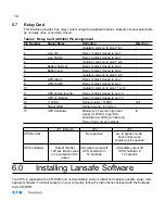
Page 16: ...onnection 8 AC Fail AC Fail relay contact Out 9 Power Source V 8 to 24 volts DC power Out USB Port The UPS is also equipped with a USB communication port Either the DB 9 communication port or the USB...

Page 17: ...11 UPS Online Inverter Relay contact closed to pin 10 12 UPS on Bypass Relay contact closed to pin 10 13 12VDC Signal supply 12VDC Out 14 Signal GND Signal ground Common 15 UPS Shutdown Minimum 5 seco...

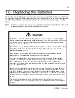
Page 18: ...ts could fall into the UPS Never allow any tool to contact both a battery terminal and the UPS cabinet or another battery terminal Do not lay tools or metal parts on top of batteries To ensure continu...

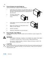
Page 19: ...w battery 6 Reinstall the metal battery cover and front panel 7 2 Recycling the Used Battery Contact your local recycling or hazardous waste centre for information on proper disposal of the used batte...

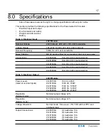
Page 20: ...se Connections 91200700A 10A IEC C14 input connector 91201000A 10A IEC C14 input connector 91201500A 10A IEC C14 input connector 91202000A 10A IEC C14 input connector 91203000A 16A IEC C20 input conne...

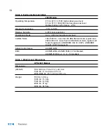
Page 21: ...1500 VA Less than 48 dBA Normal mode typical load 2000 3000 VA Less than 54 dBA Normal mode typical load Surge Suppression ANSI IEEE C62 41 1991 ANSI IEEE C62 45 1987 Category B Safety Conformance AS...

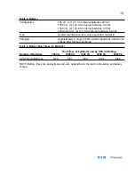
Page 22: ...ntenance free valve regulated lead acid Charging Approximately 4 hours to 90 usable capacity at nominal line voltage after full load discharge Table 9 Battery Run Times in Minutes Run Times at Full Ha...

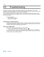
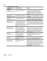
Page 23: ...ction explains UPS alarms and conditions How to silence an alarm Audible Alarms and UPS Conditions The UPS has an audible alarm feature to alert you of potential power problems When the alarm is activ...

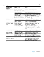
Page 24: ...rged because of to charge the battery Perform a battery test time long term storage see Section 4 0 Configuration frequent power outages If the battery test fails see Section 7 0 end of battery life R...

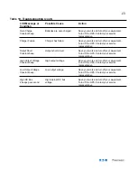
Page 25: ...rger capacity The UPS switches to Bypass UPS mode Battery Overload The UPS is on battery and Shutdown is imminent 30 seconds Save your 2 beeps per second the power requirements work and turn off your...

Page 26: ...short circuit Save your work and turn off your equipment Constant beep Turn off the UPS Contact your service representative High Output Voltage High output voltage Save your work and turn off your eq...

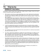
Page 27: ...ance with EPQ recommended standard installation procedures EPQ shall thereupon correct any defects due to faulty materials and or work manship 3 Any modification made to the product other than those m...

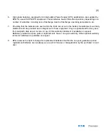
Page 28: ...tery manufacturer s warranty statement and are provided as an integral part of new equipment they are guaranteed for two years from despatch date as per invoice A copy of this warranty statement is av...

Page 29: ...Eaton Power Quality Pty Ltd 13 Healey Road DANDENONG VIC 3175 AUSTRALIA AFFI X PO STAG E STAM P...

Page 30: ...ail from Eaton Powerware at least three 3 times per year No 1 Where did you purchase this Powerware UPS from Retail Store Computer Store Eaton Powerware Distributor Direct from Eaton Powerware Electri...

Page 31: ...vice Offices Adelaide Brisbane PO Box 481 Marlestone Business Centre Unit 4 11 Donkin Street SA 5033 West End QLD 4101 Phone 08 8347 3622 Phone 07 3891 1211 Fax 08 8445 6328 Fax 07 3891 2492 Melbourne...

Page 32: ...rs to 3kVA Hardwired Single Phase Power Conditioners to 22 5kVA Constant Voltage Transformers to 7 5kVA AC DC switching and linear Power Supplies CVDC Constant Voltage Ferroresonant Power Supplies Low...

Reviews: