14
5.7
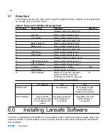
Relay Card
This interface provides true relay contact output to peripheral devices. Outputs are user-selectable
as normally open or normally closed.
Table 2. Relay Card (AS/400) Pin Assignment
Pin Number
Signal Name
Definition
Direction
1
-
Isolated common to pins 2 & 3
-
2
Line OK
Relay contact; closed to pin 1
-
3
Line Failure
Relay contact; closed to pin 1
-
4
-
Isolated common to pins 5 & 6
-
5
Battery Normal
Relay contact; closed to pin 4
-
6
Battery Low
Relay contact; closed to pin 4
-
7
-
Isolated common to pins 8 & 9
-
8
UPS Alarm
Relay contact; closed to pin 7
-
9
UPS On/OK
Relay contact; closed to pin 7
-
10
-
Isolated common to pins 11 & 12
-
11
UPS Online/Inverter
Relay contact; closed to pin 10
-
12
UPS on Bypass
Relay contact; closed to pin 10
-
13
+12VDC
Signal 12VDC
Out
14
Signal GND
Signal ground - Common
-
15
UPS Shutdown
Minimum 5 seconds high level
In
signal (+12VDC) to perform
shutdown according to following
Relay Card Jumper settings:
JP1 (default)
JP2
JP3
UPS Normal
-
No response
Go to bypass mode,
back online when
shutdown pins opened
UPS on Battery
Output off after
Immediate output off
Immediate output off
120 sec. Back online
UPS shutdown in
UPS shutdown in
on resumption of AC
12 seconds
12 seconds
power
6.0
Installing Lansafe Software
Your UPS is supplied with a CD-ROM and communication cable to install and operate Lansafe power man-
agement software. To install Lansafe on your computer, follow the instructions enclosed with the Software
Suite CD-ROM.


