background image

Safety Warnings

Eaton 9135 5000/6000 VA UPS User’s Guide 164201726—Rev 4

www.eaton.com/powerquality

8

AVVERTENZA

l

L'UPS contiene la propria fonte di energia (batterie). Le prese d'uscita dell'UPS possono essere 
sotto tensione anche quando l'UPS non è collegato all'alimentazione elettrica CA.

l

Nei modelli da 230 V è possibile che le prese d'uscita rimangano sotto tensione. Se la fonte di 

alimentazione in entrata dell'installazione è costituita da un collegamento linea-neutro (come 

accade nella maggior parte delle installazioni europee), la tensione delle prese d'uscita è pari a 

0 V. Con un cablaggio in entrata del tipo linea-linea, la tensione sulle prese d'uscita è 115 V (con 

misurazione effettuata da linea a terra o da linea a neutro in base al cablaggio dell'UPS).

l

Non rimuovere nè scollegare il cavo di ingresso quando il gruppo statico di continuità è acceso 

poichè in tal modo si disattiverebbe il collegamento a terra di sicurezza del gruppo statico di 

continuità e dell'apparecchiatura ad esso collegata.

l

Per ridurre il rischio di incendio o di scossa elettrica, installare il gruppo statico di continuità in un 
ambiente interno a temperatura ed umidità controllata, privo di agenti contaminanti conduttivi. 
La temperatura ambiente non deve superare i 40°C. Non utilizzare l'unità in prossimità di acqua 
o in presenza di umidità eccessiva (95% max).

ATTENZIONE

l

Le batterie possono comportare un rischio di scossa elettrica o di ustione in seguito a un'elevata 
corrente di corto circuito. Osservare le dovute precauzioni. L'assistenza deve essere eseguita 
da personale qualificato esperto di batterie e delle necessarie precauzioni. Tenere il personale 
non autorizzato lontano dalle batterie.

l

Le batterie devono essere smaltite in modo corretto. Per i requisiti di smaltimento fare 

riferimento alle disposizioni locali.

l

Non gettare mai le batterie nel fuoco poichè potrebbero esplodere se esposte alle fiamme.

l

Sostituire le batterie con altre dello stesso numero e tipo di quelle originariamente installate 
nell'UPS.

Viktig Sikkerhetsinformasion

VIKTIGE SIKKERHETSINSTRUKSJONER — GJEM DISSE INSTRUKSJONENE

Denne håndboken inneholder viktige instruksjoner som du bør overholde ved montering og 

vedlikehold av UPS-enheten og batteriene. Les alle instruksjoner før utstyret tas i bruk, og gjem 

håndboken til fremtidig referanse.

FARLIG

Denne UPS'en inneholder LIVSFARLIGE SPENNINGER. All reparasjon og service må kun utføres 

av AUTORISERT SERVICEPERSONALE. BRUKERE KAN IKKE UTFØRE SERVICE PÅ NOEN 

AV DELENE i UPS'en.

Summary of Contents for Powerware 9135

Page 1: ...Eaton 9135 Two in One UPSUPS 5000 6000 VA User s Guide ...

Page 2: ...20 Espoo Finland Phone 358 9 452 661 Fax 358 9 452 665 68 Eaton FERRUPS and Intelligent Power Protector are registered trademarks of Eaton Corporation or its subsidiaries and affiliates IBM and AS 400 is a registered trademark International Business Machines Corporation Microsoft and Windows are registered trademarks of Microsoft Corporation in the United States and other countries National Electr...

Page 3: ...stalled and used in accordance with the instruction manual may cause harmful interference to radio communications Operation of this equipment in a residential area is likely to cause harmful interference in which case the user will be required to correct the interference at his own expense EN 62040 2 Some configurations are classified under EN 62040 2 as Category C2 UPS For these configurations th...

Page 4: ...tion such as important operating and maintenance instructions This symbol indicates that you should not discard the UPS or the UPS batteries in the trash This product contains sealed lead acid batteries and must be disposed of properly For more information contact your local recycling reuse or hazardous waste center This symbol indicates that you should not discard waste electrical or electronic e...

Page 5: ...nnections 26 Recommended Upstream Protection 27 Required Cable Cross Sections 27 Connecting the Power Cables 27 UPS Rear Panels 29 4 OPERATION 30 Control Panel Functions 30 Turning On the UPS 30 Starting the UPS on Battery 31 Turning the UPS Off 31 Operating Modes 31 Normal Mode 32 Eco Mode 32 Battery Mode 32 Bypass Mode 32 Display Functions 33 Access to Measurements 33 Access to UPS Setup 33 Acce...

Page 6: ...MAINTENANCE 41 Hot Swapping the Power Module 41 Hot Swapping the Battery Tray 41 Recycling the Used Battery or UPS 42 7 SPECIFICATIONS 44 8 TROUBLESHOOTING 46 Troubleshooting LED 46 Troubleshooting Not Requiring Eaton Service 46 Troubleshooting Requiring Eaton Service 47 Service and Support 48 9 WARRANTY 49 ...

Page 7: ...n 9135 UPS Providing outstanding performance and reliability the unique benefits of the Eaton 9135 UPS include l Online UPS design with pure sine wave output The UPS filters and regulates incoming AC power and provides consistent power to your equipment without draining the battery l Two in one form factor for using the UPS in a rack mount configuration or as a standalone cabinet l Hours of extend...

Page 8: ... UPS wiring l Do not remove or unplug the input cord when the UPS is turned on This removes the safety ground from the UPS and the equipment connected to the UPS l To reduce the risk of fire or electric shock install this UPS in a temperature and humidity controlled indoor environment free of conductive contaminants Ambient temperature must not exceed 40 C 104 F Do not operate near water or excess...

Page 9: ...ikoen for brand og elektrisk stød Rumtemperaturen må ikke overstige 40 C UPS en bør ikke betjenes nær vand eller høj fugtighed maksimalt 95 ADVARSEL l Batterierne kan give risiko for elektrisk stød eller brandsår forårsaget af høj kortslutningsstrøm Overhold gældende forsigtighedsregler Servicering skal udføres af kvalificeret servicepersonale med kendskab til batterier og gældende forsigtighedsre...

Page 10: ...ntreinigingen aanwezig zijn De omgevingstemperatuur mag 40 C niet overschrijden Niet gebruiken in de buurt van water of bij zeer hoge vochtigheid max 95 OPGELET l Batterijen leveren gevaar op voor elektrische schokken en kunnen brandwonden veroorzaken door een grote kortsluitstroom Neem de juiste voorzorgsmaatregelen in acht Het onderhoud moet worden uitgevoerd door bevoegde onderhoudsmonteurs die...

Page 11: ...tä kosteita tiloja 95 maksimi VARO l Akut voivat aiheuttaa sähköiskun tai palovammojen vaaran johtuen suuresta oikosulkuvirrasta Noudata kaikkia asianmukaisia varotoimia Laitteen saa huoltaa vain ammattitaitoinen huoltohenkilökunta joka tuntee akut ja niihin liittyvät varotoimet Älä päästä valtuuttamatonta henkilöstöä lähelle akkuja l Akusto täytyy hävittää säädösten mukaisella tavalla Noudata pai...

Page 12: ...s dépasser 40 C Ne pas utiliser à proximité d eau ou dans une atmosphère excessivement humide 95 maximum ATTENTION l Les batteries peuvent présenter un risque de choc électrique ou de brûlure provenant d un courant de court circuit haute intensité Observez les précautions appropriées L entretien doit être réalisé par du personnel qualifié connaissant bien les batteries et les précautions nécessair...

Page 13: ...igen Die USV nicht in der Nähe von Wasser oder in extrem hoher Luftfeuchtigkeit max 95 betreiben VORSICHT l Batterien können das Risiko eines elektrischen Schlags bergen oder durch hohen Kurzschlussstrom in Brand geraten Die richtigen Vorsichtsmaßnahmen beachten Die Wartung muss von qualifiziertem Wartungspersonal durchgeführt werden das im Umgang mit Batterien geübt ist und über gute Kenntnisse d...

Page 14: ...d umidità controllata privo di agenti contaminanti conduttivi La temperatura ambiente non deve superare i 40 C Non utilizzare l unità in prossimità di acqua o in presenza di umidità eccessiva 95 max ATTENZIONE l Le batterie possono comportare un rischio di scossa elettrica o di ustione in seguito a un elevata corrente di corto circuito Osservare le dovute precauzioni L assistenza deve essere esegu...

Page 15: ...tfuktighet som er fritt for ledende forurensende stoffer Romtemperaturen må ikke overskride 40 C Den må ikke brukes i nærheten av vann eller ved meget høy luftfuktighet 95 maks FORSIKTIG l Batterier kan utgjøre en fare for elektrisk støt eller brannsår pga høy kortsluttingsstrøm Treff passende forholdsregler Service bør utføres av kvalifisert servicepersonale med kjennskap til batterier og nødvend...

Page 16: ...e excessiva máx 95 CUIDADO l As baterias podem oferecer risco de choque elétrico ou queimadura ocasionados por alta tensão com possibilidade de curto circuito Tome as precauções adequadas A manutenção deve ser realizada por pessoal qualificado com conhecimento sobre baterias e ciente das precauções exigidas Mantenha o pessoal não autorizado afastado das baterias l Siga as instruções apropriadas ao...

Page 17: ...руйте устройство около воды или в местах с повышенной влажностью макс 95 ОСТОРОЖНО l Высокое напряжение вызванное коротким замыканием в батарее может привести к поражению электрическим током или ожогу Соблюдайте меры предосторожности Техническое обслуживание должно осуществляться квалифицированным персоналом по работе с источниками питания знакомым с мерами предосторожности Не допускайте к работе ...

Page 18: ... ambiente no debe exceder los 40 C No trabaje cerca del agua o con humedad excesiva 95 máximo PRECAUCIÓN l Las baterías pueden constituir un riesgo de descarga eléctrica o quemaduras por corriente alta de corto circuito Adopte las precauciones debidas Personal calificado de servicio que conozca de baterías y esté al tanto de las precauciones requeridas debe darle servicio al equipo Mantenga al per...

Page 19: ...n Detta tar bort skyddsjordningen från både UPS enheten och den anslutna utrustningen l Minska risken för brand eller elektriska stötar genom att installera denna UPS enhet inomhus där temperatur och luftfuktighet är kontrollerade och där inga ledande föroreningar förekommer Omgivande temperatur får ej överstiga 40 C Använd inte utrustningen nära vatten eller vid hög luftfuktighet max 95 VITKTIGT ...

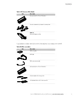
Page 20: ...ptance file a claim for concealed damage To file a claim for shipping damage or concealed damage 1 File with the carrier within 15 days of receipt of the equipment 2 Send a copy of the damage claim within 15 days to your service representative Checking the Accessory Kit Verify that the following additional items are included with the UPS NOTE Check the battery recharge date on the shipping carton ...

Page 21: ...mounting kit for 19 inch 48 cm bays Two sets of pedestals with screws for tower position Optional Network Management Card Table 2 EBM Accessory Items Item Description EBM user s guide EBM cable EBM communication cable Rackmounting kit for 19 inch 48 cm bays Pedestal extenders for tower position Joining bracket and screws for tower position Table 1 UPS Accessory Kit Continued Item Description ...

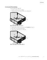
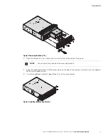
Page 22: ... is off and unplugged 2 Remove the two screws from the battery switch see Figure 2 Figure 2 Removing the Battery Switch Screws 3 Slide the battery connector so that you can read Connected see Figure 3 4 Reinstall the two screws removed in Step 2 5 Continue to the following section UPS Setup Figure 3 Connecting the Internal Battery Connector Two Screws Battery Switch Two Screws Battery Switch ...

Page 23: ... includes l Left and right sliding rail assemblies l 20 M4x6 mm Phillips flat head screws l 4 M4x10 mm Phillips round head screws l 4 M6x12 mm Phillips round head screws l 8 M6x12 mm Phillips flat head screws l 2 mounting brackets l 2 rear hold down brackets Installing the Rail Kit CAUTION l DO NOT install the UPS or EBM in a hermetically closed environment without any exchange of air l The UPS an...

Page 24: ...90 counterclockwise see Figure 4 Figure 4 Adjusting the UPS Control Panel Orientation 2 Recommended Remove the UPS battery tray see Figure 5 Remove the UPS front cover six screws Place the front panel above the UPS Remove the two battery retaining brackets four screws Slightly pull the battery tray then lift it to extract it NOTE A ribbon cable connects the control panel to the UPS Do not pull on ...

Page 25: ...at stable surface with the front of the cabinet facing you 4 Align the mounting brackets with the screw holes on the side of the cabinet and secure with the supplied M4x6 mm flat head screws 5 If installing additional cabinets repeat Steps 3 and 4 for each cabinet Figure 6 Installing the Mounting Brackets NOTE You can adjust the position of the mounting brackets ...

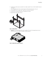
Page 26: ...he UPS in the desired location in the rack 8 Using two M6x12 mm flat head screws attach the rail to the rear of the rack 9 Secure the rail to the front of the rack with two M6x12 mm screws 10 Repeat Steps 8 and 9 for the other rail Figure 7 Installing the Rails 11 Optional Install the rear hold down brackets included with the rail kit if you need to move the rack enclosure with the UPS already rac...

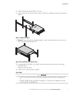
Page 27: ...e brackets to the rear rails using two screws for each bracket see Figure 10 Figure 10 Securing the Rear Hold Down Brackets 15 If you removed the UPS battery tray in Step 2 replace the battery tray and secure with the battery retaining brackets Replace the UPS front cover 16 Continue to Installing the UPS on page 24 Tower Setup CAUTION l DO NOT install the UPS or EBM in a hermetically closed envir...

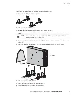
Page 28: ... the joining brackets must be installed Proceed to Step 6 3 Carefully position the cabinet upright with the UPS indicators at the top and place in the pedestals see Figure 12 4 Adjust the pedestals to the size of the UPS and secure the pedestals with the captive screws Figure 12 Tower Position with One Cabinet 5 Continue to the following section Installing the UPS 6 Install pedestal extenders for ...

Page 29: ...osition 4 on the pedestal see Figure 14 Figure 13 Extending the Pedestals for Two Cabinets Figure 14 Extending the Pedestals for Three or More Cabinets 7 Carefully position the cabinet upright with the UPS indicators at the top and place in the pedestals see Figure 15 8 Adjust the pedestals to the size of the UPS and secure the pedestals with the captive screws Figure 15 Tower Position with Two Ca...

Page 30: ... not make unauthorized changes to the UPS or accessories otherwise damage may occur to your equipment and void your warranty See UPS Rear Panels on page 29 for the rear panel of each model To install the UPS and optional EBMs 1 If installing an optional EBM continue to Step 2 otherwise continue to Step 4 2 Verify that the EBM battery circuit breaker is OFF 3 Plug the EBM cable into the battery con...

Page 31: ...supplied in the accessory kit For more information about communication options see Chapter 5 Additional Features on page 38 Figure 18 Installing the RS 232 Serial Cable 5 If you are installing a remote power off RPO switch see the following section RPO Installation to install the switch before powering on the UPS 6 Continue to UPS Electrical Connections on page 26 EBM Communication Cable EBM Cable...

Page 32: ...ge 5 Vdc to 27 Vdc Current 10 mA maximum UPS Electrical Connections WARNING Only qualified service personnel such as a licensed electrician shall perform the electrical installation Risk of electrical shock CAUTION l For UPS models with hardwired outputs overcurrent protection for the output AC circuit s is to be provided by others l For UPS models with hardwired outputs suitably rated disconnect ...

Page 33: ...the required cable cross sections Continue to the following section Connecting the Power Cables Connecting the Power Cables WARNING l Only qualified service personnel such as a licensed electrician shall perform the electrical connection Risk of electrical shock l Before carrying out any connection check that the battery circuit breaker and UPStream protection device utility input are OFF O l Use ...

Page 34: ...gh the output cable opening 4 Connect the three wires to the output terminal block see Figure 22 Figure 22 Installing the Input and Output Cables 5 Replace the terminal block cover and tighten the cables 6 Secure the terminal block cover with the two screws removed in Step 1 7 Plug the equipment to be protected into the appropriate UPS output receptacles see Figure 23 IMPORTANT If more than one lo...

Page 35: ... Cords UPS Rear Panels This section shows the rear panels of the Eaton 9135 UPS models Figure 24 5000 6000 VA 2 0 0 2 5 0 V 2 4 A R Y B A T T E C O N N E C T O 1 8 0 4 L6 30 Receptacles Communication Bay Relay Port RPO Port EBM RJ 11 Connector Output Terminal Block Input Cord with L6 30P EBM Battery Connector USB Port RS 232 Port ...

Page 36: ...Turning On the UPS To turn on the UPS 1 Verify that the UPS internal battery connector is connected see Figure 2 on page 16 2 Set the UPStream circuit breaker not included to the On position The equipment is powered by utility power but not protected by the UPS Batteries are recharging An eight hour recharge period is necessary to get full backup time The and indicators illuminate To change the fa...

Page 37: ... Off To shut down the UPS 1 Press the button for approximately three seconds The UPS beeps once and the load is no longer protected by the UPS It is powered by utility power If the UPS is set in frequency converter mode the equipment will not be powered If the utility power is out of tolerance the UPS will generate a 10 ms output calibrated break 2 For a full shutdown of UPS and connected load the...

Page 38: ...lied by the battery The display shows the remaining battery backup time If battery capacity becomes low while in Battery mode the alarm beeps every three seconds Immediately complete and save your work to prevent data loss and similar difficulties When the utility power returns the UPS transfers to Normal mode operation while the battery recharges End of backup time all indicators turn off The ala...

Page 39: ...ents for voltage current frequency power output and battery capacity Access to UPS Setup To access the UPS Setup menu 1 Scroll to the UPS Setup menu by pressing the button 2 Press the button to access the menu Status and Alarms Measurements Maintenance UPS Setup UPS Input Measurements Status and Alarms UPS Output Measurements Battery Measurements Local Settings Output Settings ON OFF Settings Batt...

Page 40: ... Voltage G Models 208V 200V 208V 220V 240V 250V Freq Converter Disable Enable Output Frequency G Models 60 Hz 60 Hz User selectable under frequency converter mode Eco Mode Disable Enable See page 32 Slew Rate 1 Hz sec 0 5 Hz sec Bypass Transfer If bypass Ac nok Yes No Transfer to bypass if utility power is out of tolerance Interrupt Time 10 ms 20 ms 200 ms Break time calibration during load transf...

Page 41: ...the shutdown sequence Auto Restart Enable Disable UPS restarts automatically when utility power is restored Energy Saving Disable Enable Automatic shutdown on battery if output load level 10 Sleep Mode Enable Disable Remote Command Enable Disable Enables consideration of shutdown or restart orders from software to be authorized Table 8 Battery Settings Function Factory Setting Options Comments Aut...

Page 42: ... see Table 10 Table 9 Maintenance Settings Function Sub Function Option Display Comments Model Power Module SN xxxxxxxxx SOFT xxx Serial number Soft version Frame Alarm History Read Description Date Hour Alarm xxx 10 alarms can be stored automatically Erase No Yes Manual Batt Test Manual Battery Test No Yes Led Buzzer Test Led Buzzer Test No Yes Life Cycle Monitoring LCM Enable Disable Life cyclin...

Page 43: ...e in the Status and Alarm menu to temporarily cancel the alarm status The alert will be repeated twice every 30 days l For permanent reset press the button for at least three seconds while in the LCM warning menu to permanently cancel the LCM event At any time l To disable all LCM messages select disable all while in the LCM menu Be careful if you disable all LCM messages you will not be aware of ...

Page 44: ...ation bay is compatible with the optional Network Management Card USB Port The UPS can communicate with a USB compliant computer using Intelligent Power Protector IPP or other compliant human interface device HID power management software compatible with Microsoft Windows 2000 and XP operating systems that support HID devices To establish communication between the UPS and a computer 1 The USB port...

Page 45: ...um l Power 62 5 VA 30W Example for 48 Vdc Imax 625 mA Figure 32 identifies the cable pins and Table 11 describes the pin functions Figure 32 Communication Port Table 11 Communication Port Pin Assignment Pin Number Function 1 2 Not used 3 Remote Power off signal 5 27 Vdc 10 mA max 4 Operation on mains not on battery 5 User common 6 Operation on automatic bypass 7 Low Battery 8 Load protected 9 Oper...

Page 46: ...etwork Management Card Optional It is not necessary to shut down the UPS before installing a communication card 1 Remove the slot cover secured by two screws 2 Insert the communication card into the slot 3 Secure the card with both screws Figure 33 Network Management Card Communication Card restricted access ...

Page 47: ... module then lift it to extract it 5 Replace the faulty power module with one of the same power rating 5000 VA or 6000 VA and secure with the power module brackets 6 Replace the UPS front cover Hot Swapping the Battery Tray CAUTION l Batteries can present a risk of electrical shock or burn from high short circuit current Observe proper precautions Servicing should be performed by qualified service...

Page 48: ...dous waste center for information on proper disposal of the used battery or UPS WARNING l Do not dispose of the battery or batteries in a fire Batteries may explode Proper disposal of batteries is required Refer to your local codes for disposal requirements l Do not open or mutilate the battery or batteries Released electrolyte is harmful to the skin and eyes It may be toxic CAUTION Do not discard...

Page 49: ...00 VA UPS User s Guide 164201726 Rev 4 www eaton com powerquality 43 CAUTION Do not discard waste electrical or electronic equipment WEEE in the trash For proper disposal contact your local recycling reuse or hazardous waste center ...

Page 50: ...17 5 x5 1 x29 2 57 kg 125 7 lb 6000 VA UPS UPS Power Module 198x127x603 mm 7 8 x 5 x 23 7 12 kg 26 5 lb UPS Internal Battery 214 5x116x498 mm 8 4 x 4 6 x 19 6 30 5 kg 67 2 lb EBM 444 5x130 6x650 mm 17 5 x 5 1 x 25 6 70 5 kg 155 4 lb Table 14 Power Connections Models Input Connection Output Receptacles PW9135G5000 XL3UHW PW9135G5000 XL3U 3 05m 10 ft L6 30P power cord 4 NEMA L6 30R PW9135G6000 XL3UH...

Page 51: ... Configuration 2 strings of 15 12V 5 5 Ah internal batteries Type Sealed maintenance free lead acid Table 17 Battery Runtimes UPS UPS Internal Batteries 1 EBM 2 EBMs 3 EBMs 4 EBMs 5000 VA 5 min 22 min 41 min 1 hr 2 min 1 hr 23 min 6000 VA 4 min 17 min 33 min 50 min 1 hr 7 min NOTE Battery times are approximate and vary depending on the load configuration and battery charge ...

Page 52: ...rvice and support Troubleshooting LED Press the esc button to stop the audible alarm Figure 36 Troubleshooting LED Troubleshooting Not Requiring Eaton Service Figure 37 Environment Fault NOTE In case of MULTIPLE FAULT press the button and the button to get access to further details In case of LCM WARNING see Life Cycle Monitoring on page 36 Escape Up Down Enter ...

Page 53: ...nnected to the correct terminals Check AC wiring NO POWER MODULE The power module is not inserted Check power module connections see page 43 NO BATTERY MODULE The battery tray is incorrectly connected Check battery connections see page 43 INV THERM OVERLOAD The UPS shuts down automatically because of a major overload Check the power drawn by the connected devices and disconnect any non priority de...

Page 54: ...mber This number must appear on the outside of the package and on the Bill Of Lading if applicable Use the original packaging or request packaging from the Help Desk or distributor Units damaged in shipment as a result of improper packaging are not covered under warranty A replacement or repair unit will be shipped freight prepaid for all warrantied units Display Problem Correction POWER MODULE FA...

Page 55: ...receives notice of the warranty claim In such case the End User must return at Company s expense the defective Warranted Item to Company in the same packaging as the replacement Warranted Item received by the End User or as otherwise instructed by Company If Company does not receive the defective Warranted Item Company will either charge the End User s credit card or send the End User an invoice w...

Page 56: ...hall Company be liable in contract in tort including negligence or strict liability or otherwise for damage to property or equipment other than the Products including loss of profits or revenue loss of use of Products loss of data cost of capital claims of customers of the End User or any special indirect incidental or consequential damages whatsoever The total cumulative liability of Company here...

Page 57: ... 3 The installation of the UPS complies with all applicable electrical and safety codes described by the National Electrical Code NEC 4 The UPS was used under normal operating conditions and in accordance with all labels and instructions and 5 The UPS was not damaged by accident other than AC power line transient misuse or abuse l Cumulative Limits to be paid by Guarantor under this Load Protectio...

Page 58: ...ollow the Product s operation and maintenance manual and protect against further damage to the Product if there is a covered defect OTHER LIMITATIONS Company s obligations under this Guaranty are expressly conditioned upon receipt by Company of all payments due to it including interest charges if any During such time as Company has not eceived payment of any amount due to it for the Product in acc...

Reviews: