background image

SAFETY WARNINGS

Eaton 9140 UPS (7.5–10 kVA) User's Guide  

S

  164201622 Rev 3

 www.eaton.com/powerquality

17

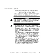
Advertencias de Seguridad

INSTRUCCIONES DE SEGURIDAD IMPORTANTES

GUARDE ESTAS INSTRUCCIONES

Este manual contiene instrucciones importantes que debe seguir durante la instalación y el
mantenimiento del SIE y de las baterías. Por favor, lea todas las instrucciones antes de
poner en funcionamiento el equipo y guarde este manual para referencia en el futuro.

P


E


L


I


G


R


O

Este SIE contiene VOLTAJES MORTALES. Todas las reparaciones y el servicio técnico deben
ser efectuados SOLAMENTE POR PERSONAL DE SERVICIO TÉCNICO AUTORIZADO. No hay
NINGUNA PARTE QUE EL USUARIO PUEDA REPARAR dentro del SIE.

A


D


V


E


R


T


E


N


C


I


A

S

Este SIE contiene su propia fuente de energía (baterías). Los receptáculos de salida
pueden transportar voltaje activo aun cuando el SIE no esté conectado con una fuente de
CA.

S

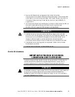
Es posible que los receptáculos de salida tengan voltajes activos aún en modo Standby
(de espera) o REPO. Por ejemplo, con el cableado de entrada de línea a línea (208V línea
a línea, monofásico), el voltaje en los receptáculos de salida es de 110–120V (medido de
neutro a tierra).

S

No retire o desenchufe el cable de entrada mientras el SIE se encuentre encendido. Esto
suprime la descarga a tierra de seguridad del SIE y de los equipos conectados al SIE.

S

Para reducir el riesgo de incendio o de choque eléctrico, instale este SIE en un lugar
cubierto, con temperatura y humedad controladas, libre de contaminantes conductores.
La temperatura ambiente no debe exceder los 40°C. No trabaje cerca del agua o con
humedad excesiva (95% máximo).

S

Para todos los modelos de SIE, la protección contra sobrecargas de corriente para el(los)
circuito(s) de entrada y salida de CA debe suministrarse por parte de terceros. Para
reducir el riesgo de incendio, realice la conexión únicamente con un circuito que se
proporcione con protección contra sobrecargas de corriente de circuito de bifurcación
para una especificación de 60 amperios (modelos 10 kVA) o 50 amperios (modelos
7.5 kVA) de acuerdo con el Código Eléctrico Nacional, ANSI/NFPA 70.

Summary of Contents for Powerware 9140

Page 1: ...Powerware Series Eaton 9140 UPS 7 5 10 kVA User s Guide...

Page 2: ...s les exigences du Reglement sur le mat riel brouilleur du Canada EN 50091 2 Some configurations are classified under EN 50091 2 as Class A UPS for Unrestricted Sales Distribution For these configurat...

Page 3: ...or use within certain voltage limits 93 68 EEC Amending Directive 73 23 EEC 89 336 EEC Council Directive relating to electromagnetic compatibility 92 31 EEC Amending Directive 89 336 EEC relating to E...

Page 4: ...ion such as important operating and maintenance instructions This symbol indicates that you should not discard the UPS or the UPS batteries in the trash This product contains sealed lead acid batterie...

Page 5: ...Checking the UPS Accessory Kit 32 Rack Setup for the UPS 33 Installing the UPS Internal Batteries 42 EBM Installation 43 UPS Installation 45 Plug Receptacle UPS Installation 45 Hardwired UPS Installat...

Page 6: ...rts 78 X Slot Cards 79 LanSafe Power Management Software 80 6 UPS Maintenance 81 UPS and Battery Care 81 Storing the UPS and Batteries 81 When to Replace Batteries 82 Replacing Batteries 82 How to Rep...

Page 7: ...itching transients and harmonic distortion Power outages can occur when you least expect it and power quality can be erratic These power problems have the potential to corrupt critical data destroy un...

Page 8: ...me and provide a warning before the end of useful battery life S Extended runtime with up to four EBMs S Start on battery capability for powering up the UPS even if utility power is not available S Ea...

Page 9: ...input cord when the UPS is turned on This removes the safety ground from the UPS and the equipment connected to the UPS S To reduce the risk of fire or electric shock install this UPS in a temperature...

Page 10: ...indvendige dele kan repareres af brugeren ADVARSEL S Denne UPS indeholder sin egen energikilde batterier Udgangsstikkene kan endog v re str mf rende n r UPS en ikke er koblet til en vekselstr msforsyn...

Page 11: ...f batterier er p kr vet Overhold g ldende lokale regler for bortskaffelsesprocedurer S Skaf dig aldrig af med batterierne ved at br nde dem Batterierne kan eksplodere ved ben ild Belangrijke Veilighei...

Page 12: ...lectrical Code ANSI NFPA 70 S Voor alle UPS modellen dienen toepasselijk geclassificeerde stroomonderbrekers voor de in en uitgangswisselstroomkringen door anderen te worden verzorgd Om brandgevaar te...

Page 13: ...ntulojohtoa kun UPS on kytkettyn T m poistaa turvamaadoituksen UPS laitteesta ja siihen liitetyst laitteistosta S V hent ksesi tulipalon ja s hk iskun vaaraa asenna t m UPS sis tiloihin joissa l mp t...

Page 14: ...s TENSIONS MORTELLES Toute op ration d entretien et de r paration doit tre EXCLUSIVEMENT CONFI E A UN PERSONNEL QUALIFI AGR AUCUNE PI CE R PARABLE PAR L UTILISATEUR ne se trouve dans l onduleur AVERTI...

Page 15: ...fourni avec une protection contre les surintensit s du circuit de d rivation de 50 amp res d intensit nominale conform ment au National Electrical Code ANSI NFPA 70 S Pour respecter les normes et r gl...

Page 16: ...t nden unter Spannung selbst im Bereitschafts oder REPO Betrieb Zum Beispiel betr gt bei einer Verkabelung mit Au enleitern 208 V einphasige Verkabelung die Spannung an den Ausgangssteckdosen 110 120...

Page 17: ...tung muss von qualifiziertem Wartungspersonal durchgef hrt werden das im Umgang mit Batterien ge bt ist und ber gute Kenntnisse der erforderlichen Vorsichtsma nahmen verf gt Nicht autorisiertes Person...

Page 18: ...di incendio effettuare il collegamento soltanto a un circuito dotato di una protezione da sovraccarico per il circuito derivato per 60 A per i modelli da 10 kVA o 50 A per i modelli da 7 5 kVA come st...

Page 19: ...e sikkerhetsjordingen fjernes fra UPS en og det utstyret som er forbundet med den S For redusere fare for brann eller elektriske st t b r denne UPS en installeres i et innend rs milj med kontrollert t...

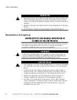
Page 20: ...o futuramente CUIDADO A UPS cont m VOLTAGEM MORTAL Todos os reparos e assist ncia t cnica devem ser executados SOMENTE POR PESSOAL DA ASSIST NCIA T CNICA AUTORIZADO N o h nenhuma PE A QUE POSSA SER RE...

Page 21: ...rrente de circuito de deriva o para 50 amperes de acordo com o National Electrical Code ANSI NFPA 70 S Para obedecer aos padr es internacionais e s regulamenta es de cabeamento a soma da corrente de v...

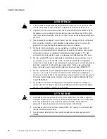
Page 22: ...SAFETY WARNINGS Eaton 9140 UPS 7 5 10 kVA User s Guide S 164201622 Rev 3 www eaton com powerquality 16 S S S 40 95 S S S 3 5 S S S...

Page 23: ...a n en modo Standby de espera o REPO Por ejemplo con el cableado de entrada de l nea a l nea 208V l nea a l nea monof sico el voltaje en los recept culos de salida es de 110 120V medido de neutro a ti...

Page 24: ...o de las precauciones requeridas debe darle servicio al equipo Mantenga al personal no autorizado alejado de las bater as S Es necesario desechar las bater as de un modo adecuado Consulte las normas l...

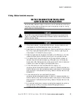
Page 25: ...0 ampere 7 5 kVA modeller i enlighet med National Electrical Code ANSI NFPA 70 S F r alla UPS modeller g ller att l mpligt klassade str mbrytare f r de utg ende v xelstr mskretsarna skall levereras av...

Page 26: ...SAFETY WARNINGS Eaton 9140 UPS 7 5 10 kVA User s Guide S 164201622 Rev 3 www eaton com powerquality 20...

Page 27: ...pment has been damaged during shipment keep the shipping cartons and packing materials for the carrier or place of purchase and file a claim for shipping damage If you discover damage after acceptance...

Page 28: ...y kit are packaged in individual cartons Do not install the batteries until after the cabinet is installed in the rack Use care when moving and opening the cartons Leave the components packaged until...

Page 29: ...installed 2 front mounting brackets 2 rear mounting brackets 12 M4 flat head screws plus 2 extra S Rails and fasteners 2 sliding rail assemblies left and right 4 adapter plates for 7 1 mm round hole...

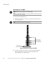
Page 30: ...optional EBM rail kit 1 Select the proper holes in the rack for positioning the EBM in the rack see Figure 2 NOTE The EBM takes up position 1 through position 9 Position 2 Position 5 Position 8 Screw...

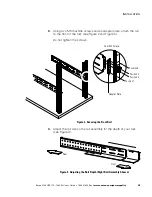
Page 31: ...tach the rail to the front of the rack see Figure 2 and Figure 3 Do not tighten the screws Front M5 Screws Position 5 Position 4 Position 6 Position 1 Adapter Plate Figure 3 Securing the Front Rail 4...

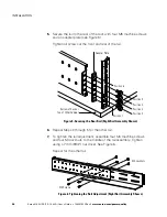
Page 32: ...ition 3 Position 5 Adapter Plate Position 6 Position 1 Bottom of Rack or Top of Other Cabinet Figure 5 Securing the Rear Rail Right Rail Assembly Shown 6 Repeat Steps 3 through 5 for the other rail 7...

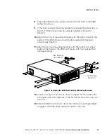
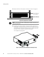
Page 33: ...the EBM and secure with eight supplied M4 flat head screws see Figure 7 11 Align the two rear mounting brackets with the lowest two screw holes on the sides of the EBM and secure with four supplied M...

Page 34: ...ont of the EBM NOTE To install the optional seismic mounting brackets the length of the rails must be between 28 5 and 32 inches 15 If installing the optional seismic mounting brackets align the two E...

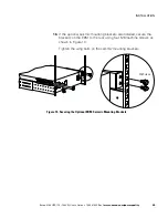
Page 35: ...uality 29 16 If the optional seismic mounting brackets are installed secure the brackets on the EBM to the rack using four M6 machine screws as shown in Figure 10 Tighten the wing bolts on the seismic...

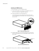
Page 36: ...tion see Figure 26 on page 44 2 Remove the EBM front cover see Figure 11 To remove the front cover loosen the two front cover screws Grasp the fingergrips on both sides of the cover and pull the cover...

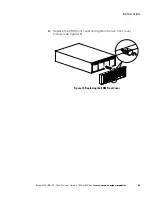
Page 37: ...N Eaton 9140 UPS 7 5 10 kVA User s Guide S 164201622 Rev 3 www eaton com powerquality 31 4 Replace the EBM front cover and tighten the two front cover screws see Figure 13 Figure 13 Replacing the EBM...

Page 38: ...rackets and fasteners if not already installed 4 front mounting brackets 2 rear mounting brackets 20 M4 flat head screws plus 2 extra S Rails and fasteners 2 sliding rail assemblies left and right 4 a...

Page 39: ...stall the optional EBM s in the lower part of the rack with the UPS directly above the EBM s To install the UPS rail kit 1 Select the proper holes in the rack for positioning the UPS in the rack see F...

Page 40: ...ength of the rails see Figure 16 and loosely install the fasteners see Figure 18 before continuing to Step 3 3 Using two M5 machine screws and an adapter plate attach the rail to the front of the rack...

Page 41: ...Figure 16 Adjusting the Rail Depth Right Rail Assembly Shown 5 Secure the rail to the rear of the rack with four M5 machine screws and an adapter plate see Figure 17 Tighten all screws at the front an...

Page 42: ...through 5 for the other rail 7 To tighten the rail adjustment assemble four M4 machine screws and four M4 locknuts to the middle of the rail assembly Tighten using a 7 mm 9 32 nut driver See Figure 1...

Page 43: ...the UPS front cover and the electronics module and set them aside see Figure 19 To remove the UPS front cover loosen the two front cover screws Grasp the fingergrips on both sides of the cover and pu...

Page 44: ...ntinue to Step 11 11 Align the four front mounting brackets with the screw holes on the sides of the UPS and secure with 16 supplied M4 flat head screws see Figure 20 12 Align the two rear mounting br...

Page 45: ...If the rack holes are round use six clip nuts 14 Slide the UPS into the rack Verify that the rear mounting brackets engage in and slide easily along the inside of the rails 15 Secure the front of the...

Page 46: ...st be between 28 5 and 32 inches 16 If installing the optional seismic mounting brackets align the two UPS seismic mounting brackets with the screw holes on the sides of the UPS above the rear mountin...

Page 47: ...shown in Figure 23 Verify that the vent holes on the sides of the UPS are not covered by the seismic mounting brackets Tighten the wing bolts on the seismic mounting brackets M6 Screws Vent Holes Figu...

Page 48: ...e 26 on page 44 2 Slide the battery trays into the cabinet see Figure 24 Push each tray in until the battery tray lock on the handle catches to lock the tray in place Battery Tray Lock Figure 24 Insta...

Page 49: ...e retention clip from the UPS battery connector Retain the clip and two screws 3 Remove the cable retention clip from all EBM battery connectors except on the EBM installed in the lowest position in t...

Page 50: ...VA User s Guide S 164201622 Rev 3 www eaton com powerquality 44 UPS EBM EBM EBM Battery Connectors Output Circuit Breakers Battery Circuit Breakers EBM Cable UPS Battery Connector Cable Retention Clip...

Page 51: ...kVA models or 50A 7 5 kVA models circuit with short circuit and overcurrent protection S 200 240 Vac S 50 60 Hz S The breaker must be wall mounted and be readily accessible to the operator S Flexible...

Page 52: ...see Figure 27 5 Make any necessary provisions for cord retention and strain relief 6 If an emergency power off disconnect switch is required by local codes see REPO and ROO Installation on page 58 to...

Page 53: ...owerquality 47 USB Port Communication Port REPO Connector 4 20A 250V Output Circuit Breakers 4 C19 Output Receptacles IEC 309 60A Input Power Cord IEC 309 60A Output Power Cord EBM Battery Connector X...

Page 54: ...er to your equipment If the alarm beeps or a UPS alarm indicator stays on see Troubleshooting on page 95 11 If you installed an optional REPO or ROO test the REPO or ROO function Activate the external...

Page 55: ...t with short circuit and overcurrent protection For three phase 30A 10 kVA models or 20A 7 5 kVA models circuit with short circuit and overcurrent protection A separate single phase input must have a...

Page 56: ...lutely sure there is no power 4 Remove the input and output terminal block covers and retain see Figure 28 REPO Connector USB Port Communication Port 4 20A 250V Output Circuit Breakers 3 C19 Output Re...

Page 57: ...three phase dual input feed see Figure 31 remove the short jumper wire connecting the L1 JP and L pins so that you can connect the second feed to the input bypass terminal block later in this procedur...

Page 58: ...INSTALLATION Eaton 9140 UPS 7 5 10 kVA User s Guide S 164201622 Rev 3 www eaton com powerquality 52 Figure 29 Single Input Feed Single Phase Figure 30 Dual Input Feed Single Phase...

Page 59: ...inal block covers for the input input bypass dual input feed only and output conduit using a Greenlee punch or similar device The holes accommodate up to 2 IMC conduit 7 Pull the input input bypass du...

Page 60: ...2 L2 In 3 L3 In 4 Neutral In2 5 Input Ground3 1 Use 13 3 mm2 6 AWG 90_C copper wire minimum For ease of installation use appropriately sized ferrules on the end of each wire 2 For single phase 208V o...

Page 61: ...g Tightening Torque Input Bypass 1 L1 JP 13 3 mm2 6 AWG 1 8 Nm 16 lb in 2 Line In 3 Neutral In 4 Input Bypass Ground Use 13 3 mm2 6 AWG 90_C copper wire minimum For ease of installation use appropriat...

Page 62: ...g the UPS in this configuration is NOT recommended and could result in unintended upstream breaker tripping and overheating of the input wiring if the breaker and wiring are sized for three phase inpu...

Page 63: ...he factory set defaults see User Settings on page 64 21 Turn the UPS on by selecting MENU from the system status screen then select CONTROL OUTPUT CONTROL UPS TO ONLINE and OK to confirm The indicator...

Page 64: ...ion Figure 35 REPO ROO Connection WARNING The REPO ROO circuit is an IEC 60950 safety extra low voltage SELV circuit This circuit must be separated from any hazardous voltage circuits by reinforced in...

Page 65: ...e NO Online Shutdown ROO Contact Open Contact Closed NC Online Standby NO Standby Online WARNING This connector must only be connected to an IEC 60950 safety extra low voltage SELV circuit This circui...

Page 66: ...the UPS for ROO behavior select MENU from the system status screen then select SETUP USER SETUP and CONTACT CONFIG Set CONTACT USAGE to REMOTE ON OFF Then set CONTACT TYPE to either normally open N O...

Page 67: ...transferring the UPS between modes Control Panel Functions The UPS has a four button two line graphical LCD with backlight It provides useful information about the UPS itself load status events measur...

Page 68: ...Battery condition is detected Fast Flash A battery test is in progress Yellow On The UPS is in Bypass mode Slow Flash Bypass mode in unavailable because the input utility is outside the configured by...

Page 69: ...he following table shows the basic menu structure Table 4 Menu Map for Display Functions Main Menu Submenu Display Information or Menu Function Control Output Control Turn the UPS on and off Transfer...

Page 70: ...t voltages 220V are set to 208V and input voltages 220V are set to 230V O P Voltage changes from Auto to the sensed voltage setting Auto Buzzer Alarm Enabled Disabled Enabled Battery Pack 1 through 5...

Page 71: ...crements NOTE This value sets the limits from 1 Hz to 5 Hz of the nominal output configuration 3 Hz Qualify Bypass Enabled Disabled NOTE This setting enables or disables the bypass qualification rules...

Page 72: ...gure 36 on page 61 shows the UPS front panel indicators and controls Figure 37 shows the internal circuit configuration Bypass Figure 37 Internal Circuit Configuration Normal Mode During Normal mode t...

Page 73: ...ts down the UPS automatically restarts Bypass Mode In the event of a UPS overload or internal failure the UPS transfers your equipment to utility power Battery mode is not available however the utilit...

Page 74: ...ected equipment before starting up the UPS 2 Switch on utility power where the UPS is connected 3 Wait for the front panel LCD to illuminate The LCD displays the startup screen for five seconds then d...

Page 75: ...s any button on the front panel display to activate the screen 4 Wait for the front panel LCD to illuminate The LCD displays the startup screen for five seconds then displays the system status screen...

Page 76: ...econds then displays the system status screen The fans run The indicator flashes quickly then slowly indicating that the UPS has entered Standby mode 4 Switch all output circuit breakers to the ON pos...

Page 77: ...ransfered to Standby mode 4 To shut down the UPS from Standby mode unplug or remove utility power from the UPS The UPS powers down all indicators flash slowly and the UPS shuts down completely in appr...

Page 78: ...e the setting 4 Press the button until the system status screen appears Initiating the Battery Test NOTE The batteries must be fully charged and the UPS must not be in Battery mode to perform the batt...

Page 79: ...iewing the Battery Test Report To view a report of the latest battery test select MENU from the system status screen then select CONTROL BATTERY TEST and TEST REPORT Transferring the UPS Between Modes...

Page 80: ...OPERATION Eaton 9140 UPS 7 5 10 kVA User s Guide S 164201622 Rev 3 www eaton com powerquality 74...

Page 81: ...the USB port or the RS 232 DB 9 communication port may be used to monitor the UPS however they cannot operate simultaneously The service DB 9 port is used only to upgrade the firmware The X Slot comm...

Page 82: ...On Off The Eaton 9140 includes a two position terminal that can be either left open or configured one of two ways S As a remote emergency power off REPO contact that allows power to be switched off a...

Page 83: ...e off signal that de energizes the load NOTE To restart the UPS return the REPO terminal to its normal deactivated state then use the front panel to return the UPS to Normal mode NOTE Disconnect the l...

Page 84: ...ower management software can exchange data with the UPS The software polls the UPS for detailed information on the status of the power environment If a power emergency occurs the software initiates th...

Page 85: ...al Monitoring Probe can be attached to obtain humidity temperature smoke alarm and security information S Relay Interface Card has isolated dry contact Form C relay outputs for UPS status Utility fail...

Page 86: ...and model select Eaton and Eaton 9140 If the Eaton brand options are not available in your version of the software select Generic UPSs for the manufacturer and Generic XCP for the model LanSafe softwa...

Page 87: ...in the UPS are rated for a 3 5 year service life The length of service life varies depending on the frequency of usage and ambient temperature Batteries used beyond expected service life will often h...

Page 88: ...other metal objects 2 Use tools with insulated handles 3 Do not lay tools or metal parts on top of batteries 4 Disconnect charging source prior to connecting or disconnecting battery terminals 5 Wear...

Page 89: ...ble from the UPS If additional EBMs are installed remove the cable retention clip and screws and unplug the EBM cable from the battery connector on each EBM 3 Remove the EBM front cover see Figure 41...

Page 90: ...ray Repeat for each battery tray in the cabinet See Recycling the Used Battery or UPS on page 89 for proper disposal 5 Slide the new battery trays into the EBM cabinet see Figure 42 Push each tray in...

Page 91: ...on the adjacent EBM 9 Reinstall the cable retention clip s and screws to hold the EBM cable s firmly in place 10 Switch all battery circuit breakers to the ON position How to Replace UPS Internal Bat...

Page 92: ...o support the tray See Figure 45 The UPS display indicates within 5 60 seconds that a battery is disconnected However if an optional EBM is installed the display does not indicate a disconnected batte...

Page 93: ...chedules the battery test to occur during the next appropriate stage in the charging cycle or immediately if possible During the battery test the indicator flashes rapidly 3 To view a report of the la...

Page 94: ...ny battery or electronics module wiring or connectors Attempting to alter wiring can cause injury NOTE DO NOT DISCONNECT the electronics module while the UPS is in Battery mode To replace the electron...

Page 95: ...module lock switch to the LOCK position The UPS automatically returns to Normal mode 7 Replace the UPS front cover and tighten the two front cover screws Recycling the Used Battery or UPS Contact your...

Page 96: ...UPS MAINTENANCE Eaton 9140 UPS 7 5 10 kVA User s Guide S 164201622 Rev 3 www eaton com powerquality 90...

Page 97: ...9140 10000 HW PW9140 7500 7 5 kVA 6 kW PW9140 7500 HW EBM Model Number PW9140 192V EBM 9 kVA 7 2 kW derated at 200V input Table 8 Weights and Dimensions UPS Extended Battery Module EBM Dimensions WxDx...

Page 98: ...ctor 0 99 Input Mode Single phase or three phase three phase option on hardwired models only Table 10 Electrical Output Regulation Nominal output voltage 2 Static 10 Dynamic Nominal Outputs 200 208 22...

Page 99: ...itude Up to 15 000 meters above sea level Heat Dissipation 2066 BTU hr maximum Audible Noise Less than 55 dBA at 5 feet with battery fully charged without horn Leakage Current 3 5 mA Communication DB...

Page 100: ...5 367 390 416 440 NOTE Charging times are approximate and are to 80 usable capacity at nominal line voltage after full load discharge Table 13 Battery Runtimes in Minutes Load 10 kVA Models UPS Intern...

Page 101: ...e Help Desk see page 99 Alarm or Condition Possible Cause Action On Battery LED is on 1 short beep every 5 seconds A utility failure has occurred and the UPS is in Battery mode The UPS is powering the...

Page 102: ...Verify that all battery trays are fully seated and locked in place If the condition persists contact your service representative Overload LED is on 1 long beep every 5 seconds Power requirements excee...

Page 103: ...the equipment is plugged into the UPS receptacles For hardwired models contact a qualified electrician to check connections to the power source The REPO switch is active or the REPO connector is miss...

Page 104: ...that the Allow Bypass user setting is Enabled see page 64 The UPS front panel is off but the fans and output are on DIP switches on the rear panel are in the down position Slide one battery tray on e...

Page 105: ...number S Firmware version number S Date of failure or problem S Symptoms of failure or problem S Customer return address and contact information If repair is required you will be given a Returned Mat...

Page 106: ...TROUBLESHOOTING Eaton 9140 UPS 7 5 10 kVA User s Guide S 164201622 Rev 3 www eaton com powerquality 100...

Page 107: ...l be repaired or replaced at a Company site or such other location as determined by Company If the Warranted Item is to be replaced by Company and the End User supplies a credit card number or purchas...

Page 108: ...WARRANTIES INCLUDING BUT NOT LIMITED TO ANY IMPLIED WARRANTIES OF MERCHANTABILITY TITLE NON INFRINGEMENT AND FITNESS FOR A PARTICULAR PURPOSE CORRECTION OF NON CONFORMITIES IN THE MANNER AND FOR THE P...

Page 109: ...the End User of any Eaton 3105 5110 5115 5125 5130 9120 9125 9130 9135 9140 9150 9155 9170 and FERRUPS Products individually and collectively the Product and cannot be transferred This Guaranty appli...

Page 110: ...ERWISE FOR DAMAGE TO PROPERTY OR EQUIPMENT OTHER THAN THE PRODUCTS INCLUDING LOSS OF PROFITS OR REVENUE LOSS OF USE OF PRODUCTS LOSS OF DATA COST OF CAPITAL CLAIMS OF CUSTOMERS OF THE END USER OR ANY...

Reviews: