COMMUNICATION
Eaton 9140 UPS (7.5–10 kVA) User's Guide
S
164201622 Rev 3
www.eaton.com/powerquality
77
S
As a remote on/off (ROO) contact
that allows the UPS to be turned on
and off from a customer-supplied switch in a remote location.
If the ROO function is configured, energizing and de-energizing the
load from the front panel is NOT available. However, transfers
between Normal mode and Bypass mode are available through the
front panel.
Two REPO/ROO positions may be used: normally-open or
normally-closed. The pins on the normally-open REPO connector are not
connected together. When this connection is closed:
S
For REPO, the logic circuitry completely shuts down the UPS, thus
preventing the power from supplying the load.
S
For ROO, a remote on signal energizes the load, and opening the
connection sends a remote off signal that de-energizes the load.
NOTE
To restart the UPS, return the REPO terminal to its normal deactivated state, then
use the front panel to return the UPS to Normal mode.
NOTE
Disconnect the load when changing the active state of the ROO contact. The load
will energize or de-energize as soon as the state is changed, depending on whether there is a
jumper installed.
C
A
U
T
I
O
N
S
The REPO must not be connected to any utility connected circuits. Reinforced insulation
to the utility is required. The REPO switch must have a minimum rating of 24 Vdc and
20 mA.
S
To ensure the UPS stops supplying power to the load during any mode of operation, the
input power must be disconnected from the UPS when the emergency power-off function
is activated.
S
When REPO is activated for a UPS with line-to-line 208V input, the output receptacles
will have 120V neutral (L2) to ground.
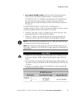
REPO/ROO Connections
Wire Function
Terminal Wire Size Rating
Suggested Wire Size
REPO/ROO
L1
0.82–0.33 mm
2
(18–22 AWG)
0.82 mm
2
(18 AWG)
L2


