INSTALLATION
Eaton
®
9140 (9910-E82/E83) UPS Installation Guide for IBM
®
Applications
S
164201715 Rev 2
www.eaton.com/ibm
34
Power Connections and Startup
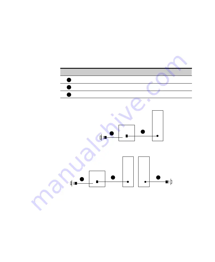
The device power cord connection(s) determines if the setup can
provide dual-redundant power to the protected device(s). See Figure 27
for a non-redundant powered device; Figure 28 shows a dual-redundant
powered device. See Table 8 on page 38 and Figure 30 through
Figure 32 beginning on page 38 for specific power connections.
Legend (Figure 27 and Figure 28)
1
UPS to utility (mains) power cord
2
PDU to UPS power cord
3
PDU to utility (mains) power cord
UPS
PDU
Mains
1
2
Figure 27. Connecting One PDU (Non-Redundant) to UPS
Mains
1
2
3
TVSS Protected or
Second UPS
UPS
PDU
Mains
PDU
Figure 28. Connecting Two PDUs (Dual-Redundant) to UPS
1.
If you are installing a UPS and non-redundant power to the device(s)
is desired, plug the PDU power cord into the UPS output receptacle
(see Figure 27) using the supplied power cord.
If you are installing a UPS and dual-redundant power to the
device(s) is desired, two PDUs are required. Plug the first PDU
power cord into the UPS output receptacle (see Figure 28) using
the supplied power cord. Then plug the second (redundant) PDU
power cord into a non-UPS protected output receptacle (mains) or
into a second UPS.


