background image

Eaton Bypass Power Module (BPM) User’s Guide P-164000628—Rev 2

www.eaton.com/powerquality

17

Chapter 3

Operation

This chapter contains information for operating the Bypass Power Module (BPM).

No Break Transfer from UPS Mode to Service Mode

CAUTION

It is critical that the following steps are followed to ensure correct and safe operation.

To turn the BPM to SERVICE:

1.

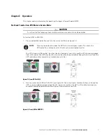
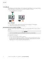
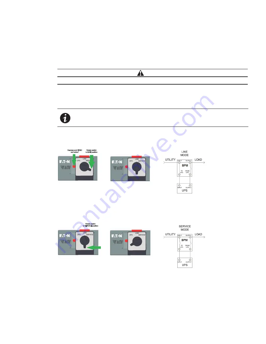
Press and hold the red button and turn the switch to LINE (see Figure 19).

The UPS is now in LINE mode. The critical load is fed directly from utility and the UPS remains energized 
from utility power. The UPS may be left in this mode while trying to troubleshoot, gather alarms from the 
UPS, or perform other preventative maintenance activities.

Figure 19. From UPS to LINE

2.

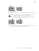
Turn the switch from LINE to SERVICE (see Figure 20). The critical load is fed directly from utility and the 
UPS is now completely disconnected from AC power. Ensure that the UPS is off and the terminals are 
completely de-energized before performing any maintenance on the UPS.

Figure 20. From LINE to SERVICE

NOTE

Pressing the red button sends the UPS into Internal Bypass mode. This allows the 
UPS output to synchronize with utility for safe, uninterrupted transfer.

Summary of Contents for Powerware 9155

Page 1: ...Eaton Bypass Power Module BPM User s Guide For use with the following l Eaton 9155 UPS 8 15 kVA l Eaton 9170 UPS 3 18 kVA l Eaton 9PX Split Phase UPS 6 10 kVA...

Page 2: ...tteries in the trash This product contains sealed lead acid batteries and must be disposed of properly For more information contact your local recycling reuse or hazardous waste center This symbol ind...

Page 3: ...unt Hardwired Installation 5 30A Linecord Input BPM Rackmount Installation 7 Wallmount Installation 8 Wallmount Hardwired BPM Installation 8 30A Wallmount Linecord BPM Installation 10 Input Current an...

Page 4: ...Table of Contents ii Eaton Bypass Power Module BPM User s Guide P 164000628 Rev 2 www eaton com powerquality...

Page 5: ...a rackmount IT environment potentially removing the need for a panelboard breakers and conduit for distribution Although the BPM is designed to be safe the bypass can carry high levels of voltage and...

Page 6: ...switch and then the critical load LINE When the switch is in the LINE position utility power is directly connected to the critical load and the output of the UPS is disconnected In this state the UPS...

Page 7: ...f electrical shock Only qualified service personnel such as a licensed electrician should perform the electrical installation CAUTION To prevent electrical shock or damage to the equipment verify that...

Page 8: ...Guide P 164000628 Rev 2 www eaton com powerquality Bypass Power Module Dimensions Figure 1 shows the dimensions of the Bypass Power Module BPM in millimeters inches Figure 1 BPM Dimensions in millimet...

Page 9: ...a rack 1 Install the 4 post rail kit included with the BPM see Figure 2 Figure 2 Install Rail Kit 2 Place the BPM on the rails and push the BPM into the rack Verify that the breakers are facing the fr...

Page 10: ...age 11 7 After wiring is complete replace the covers removed in Step 4 and Step 5 8 Push the BPM past the front of the rack to allow access for the mounting ears installation 9 Install the mounting ea...

Page 11: ...re 8 Install Rail Kit 2 Place the BPM on the rails and push the BPM into the rack leaving enough room to allow access for the mounting ears installation Verify that the breakers are facing the front o...

Page 12: ...sity power in a small form factor l Read the complete installation procedure before beginning any electrical wiring To install the BPM in a wallmount form factor 1 Select a mounting location for the b...

Page 13: ...emove the cover Remove any packing material inside the BPM 4 Remove the knockouts in the bottom of the BPM as needed for wiring see Figure 13 Figure 13 BPM Hardwired Overview Wire routing Refer to UPS...

Page 14: ...s switch within sight of the UPS 2 Use the provided wallmount brackets to firmly secure the BPM to the wall Figure 14 Figure 14 BPM with Wallmount Brackets 3 Use the provided wallmount brackets to fir...

Page 15: ...able 310 16 of the National Electrical Code NEC ANSI NFPA 70 1999 and article 220 All circuit conductors including the neutral conductor must be the same size ampacity wire Code may require a larger A...

Page 16: ...e BPM User s Guide P 164000628 Rev 2 www eaton com powerquality 5 Place the insulated wires into the two wire clips as shown Figure 15 Signal Wire Routing Signal Wire Openin g Rear of BPM Wire Clips S...

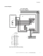
Page 17: ...ss Power Module BPM User s Guide P 164000628 Rev 2 www eaton com powerquality 13 Connection Diagrams Figure 16 Eaton 9155 UPS to BPM Connection Diagram BPM 9155 UPS Terminal Block 9155 UPS to BPM Conn...

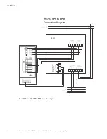
Page 18: ...aton Bypass Power Module BPM User s Guide P 164000628 Rev 2 www eaton com powerquality Figure 17 Eaton 9170 UPS to BPM Connection Diagram BPM 9170 UPS 9170 UPS to BPM Connection Diagram Contacts shown...

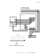
Page 19: ...eaton com powerquality 15 Figure 18 Eaton 9PX SP UPS to BPM Connection Diagram BPM 9PXSP UPS INPUT TERMINAL BLOCK L1 N OUTPUT L2 L1 N L2 9PXSP UPS Aux Contacts BPM ROO Aux Contacts BPM ROO L2 N L1 L2...

Page 20: ...Installation 16 Eaton Bypass Power Module BPM User s Guide P 164000628 Rev 2 www eaton com powerquality This page intentionally left blank...

Page 21: ...y from utility and the UPS remains energized from utility power The UPS may be left in this mode while trying to troubleshoot gather alarms from the UPS or perform other preventative maintenance activ...

Page 22: ...3 Remove the lock and tag to reset the LOTO position No Break Transfer from Service Bypass to UPS Mode After the system has been placed into SERVICE mode it must be returned to UPS state to resume no...

Page 23: ...3 Once the switch is in UPS mode and the UPS is in Normal mode online mode the system is in normal operation and prepared to provide uninterrupted power to the critical load NOTE 1 Pressing the red bu...

Page 24: ...Operation 20 Eaton Bypass Power Module BPM User s Guide P 164000628 Rev 2 www eaton com powerquality...

Page 25: ...owing specifications l Dimensions and weights l Electrical connections l Rear Panel Outlet Options Table 3 Model Dimensions HXWXD mm inch Weight kg lb BPM30XX 130 x 440 x 663 5 1 x 17 3 x 26 1 15 34 B...

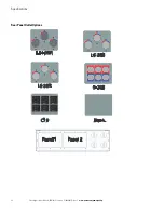
Page 26: ...Specifications 22 Eaton Bypass Power Module BPM User s Guide P 164000628 Rev 2 www eaton com powerquality Rear Panel Outlet Options L14 30R L6 30R L6 20R 5 20R C19 Blank Panel 1 Panel 2...

Page 27: ......

Page 28: ...P 164000628 2 P 164000628 2...

Reviews: