OPERATION
EATON
Powerware
®
9355 Parallel UPS (10/15 kVA) User’s Guide
S
164201601 Rev A
www.powerware.com
44
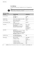
User Settings
The following table displays the options that can be changed by the
user.
NOTE
Changes to the output voltage or frequency options should be made before turning
on the UPS; otherwise, the changes do not take effect.
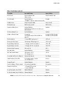
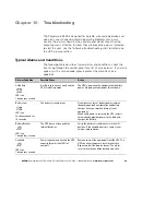
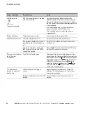
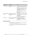
Table 3. User Settings
Description
Available Settings
Default Setting
Set Date and Time
Set Month
Date: mm/dd/yyyy
Time: 24:00
01/01/2003
00:00
Display Contrast
Adjust contrast with up/down arrow buttons
Moderate
Change Language
Select Language: <English>
Elegir idioma <Español>
English
Set NominalOutput Voltage
Output:
[120V/208V] [127V/220V]
120V/208V
Relay Config
Relay: [Alarm 1] [X-Slot 1-1/2/3/4] or
[X-Slot 2-1/2/3/4]
Setup: [Battery Low] [On Battery] [On
Bypass] [UPS ok] [custom] [empty]
Alarm 1: empty
X-Slots (1 or 2)
#1: UPS ok
#2: On Bypass
#3: Summary Alarm
#4: On Battery
Signal Inputs
[empty] [Logic]
Signal Input must be wired to the CAN Bridge
Card (see Figure 24 on page 30).
For more information, refer to “Programmable
Signal Inputs” in the
Powerware 9355 UPS
(10/15 kVA) User’s Guide
.
<empty>
Serial Port Config
Port: [X-Slot-1] [X-Slot-2/Serv]
Speed: [19200] [9600] [2400] [1200]
19200
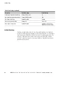
Modem Config
Modem Installation
<Not Installed>
Set Modem Call Events
Event #0
Call modem: no
Set Modem Init String
ATZ0
Set Modem Call Command
None
Set Modem Communication Password
None

