background image

TIE CABINET INSTALLATION

Eaton 9355 Tie Cabinet (20/30 kVA) Installation Guide  

S

  164201630 Rev D

 www.eaton.com/powerquality

11

18.

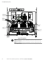
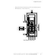
Hardwire the UPS input terminations.

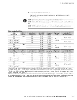
See Table 1 for specifications and Figure 6 for a detailed view of the UPS
terminal block.

NOTE  

Input neutral must be wired for proper operation or the UPS will not start.

NOTE  

The Eaton 9355 UPS is shipped as a single-feed UPS and can be converted to a dual-feed UPS in the

field.

NOTE  

DO NOT overtighten the screws; be sure to use the specified tightening torque values shown in

Table 1.

Table 1. Terminal Block Wiring

20 kVA

System Voltage

Wire

Function

Feeder Circuit

Breaker Rating

L1, L2, L3, N

Wire Size

1

Ground

Wire Size

1

Tightening

Torque

Conduit Size

2, 3

(Number of Conduits)

208

Input

100A

1 AWG

6 AWG

120 lb in

(13.5 Nm)

2.00

 Conduit (1)

220

100A

1 AWG

6 AWG

480 

(with transformer)

45A

8 AWG

10 AWG

1.00

 Conduit (1)

600 

(with transformer)

35A

8 AWG

10 AWG

208

Output

1 AWG

6 AWG

120 lb in

(13.5 Nm)

2.00

 Conduit (1)

220

1 AWG

6 AWG

480 

(with transformer)

1 AWG

6 AWG

30 kVA

System Voltage

Wire

Function

Feeder Circuit

Breaker Rating

L1, L2, L3, N

Wire Size

1

Ground

Wire Size

1

Tightening

Torque

Conduit Size

2, 3

(Number of Conduits)

208

Input

125A

1/0 AWG

6 AWG

120 lb in

(13.5 Nm)

2.00

 Conduit (1)

220

125A

1/0 AWG

6 AWG

2.00

 Conduit (1)

480 

(with transformer)

60A

6 AWG

10 AWG

1.00

 Conduit (1)

600 

(with transformer)

50A

8 AWG

10 AWG

1.00

 Conduit (1)

208

Output

1/0 AWG

6 AWG

120 lb in

(13.5 Nm)

2.00

 Conduit (1)

220

1/0 AWG

6 AWG

480

 (with transformer)

1/0 AWG

6 AWG

Use only 90

°

C-rated copper wire. Minimum wire size is based on 120/208 full load ratings applied to NEC Code Table 310‐104(A). Code may require a

larger AWG size than shown in this table because of temperature, number of conductors in the conduit, or long service runs. Follow local requirements.

Per NEC article 300‐20(a) for Ferrous Metal Raceways, all three-phase conductors must be run in the same conduit. Neutral and ground must be run in

the same conduit as the phase conductors.

Conduit is sized to accommodate one neutral conductor the same size as the phase conductor and one ground conductor. If two neutral conductors or

an oversized neutral conductor are to be installed, check the size of the conduit needed to accommodate the extra wire or size and use that conduit size
in place of the conduit size listed. Conduit sizes were chosen from NEC Table C1, type letters RHH, RHW, RHW‐2, TW, THW, THHW, THW‐2.

Summary of Contents for Powerware 9355

Page 1: ...Powerware Series Eaton 9355 Tie Cabinet Installation Guide For use with Eaton 9355 20 30 kVA UPSs...

Page 2: ......
Page 3: ...n expense ICES 003 This Class A Interference Causing Equipment meets all requirements of the Canadian Interference Causing Equipment Regulations ICES 003 Cet appareil num rique de la classe A respecte...

Page 4: ...is symbol indicates that you should not discard the UPS or the UPS batteries in the trash This product contains sealed lead acid batteries and must be disposed of properly For more information contact...

Page 5: ...4201630 Rev D www eaton com powerquality i Table of Contents 1 Introduction 1 2 Safety Warnings 3 3 Tie Cabinet Installation 7 4 Installing Options 19 Powerware Hot Sync CAN Bridge Card 19 5 Service a...

Page 6: ...TABLE OF CONTENTS Eaton 9355 Tie Cabinet 20 30 kVA Installation Guide S 164201630 Rev D www eaton com powerquality ii...

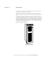
Page 7: ...wn the load A parallel load sharing system provides more capacity than a single UPS and can provide backup depending on the load and configuration In addition when one UPS is taken out of service for...

Page 8: ...INTRODUCTION Eaton 9355 Tie Cabinet 20 30 kVA Installation Guide S 164201630 Rev D www eaton com powerquality 2...

Page 9: ...electric shock install this UPS in a temperature and humidity controlled indoor environment free of conductive contaminants Ambient temperature must not exceed 40 C 104 F Do not operate near water or...

Page 10: ...taller l onduleur uniquement l int rieur dans un lieu d pourvu de mat riaux conducteurs o la temp rature et l humidit ambiantes sont contr l es La temp rature ambiante ne doit pas d passer 40 C Ne pas...

Page 11: ...ste SIE en un lugar cubierto con temperatura y humedad controladas libre de contaminantes conductores La temperatura ambiente no debe exceder los 40 C No trabaje cerca del agua o con humedad excesiva...

Page 12: ...SAFETY WARNINGS Eaton 9355 Tie Cabinet 20 30 kVA Installation Guide S 164201630 Rev D www eaton com powerquality 6...

Page 13: ...ian should perform the UPS installation and initial startup Risk of electrical shock To hardwire the Tie Cabinet 1 Verify that the electrical connections to the installation site have been properly in...

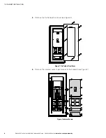
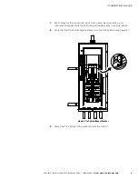
Page 14: ...0 kVA Installation Guide S 164201630 Rev D www eaton com powerquality 8 5 Remove the Tie Cabinet front cover see Figure 2 Figure 2 Tie Cabinet Front Cover 6 Remove the internal covers to gain access t...

Page 15: ...9 7 Punch holes for the conduit AC input UPS output load connection and maintenance bypass contact wires using a Greenlee punch or similar device 8 Verify that the Tie Cabinet bypass breaker is in the...

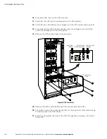
Page 16: ...the optional output circuit breaker verify that the output circuit breaker is in the OFF position 14 Remove the UPS wiring access cover and retain Battery Circuit Breaker Wiring Access Cover Input Cir...

Page 17: ...Size1 Ground Wire Size1 Tightening Torque Conduit Size2 3 Number of Conduits 208 Input 125A 1 0 AWG 6 AWG 120 lb in 13 5 Nm 2 00 Conduit 1 220 125A 1 0 AWG 6 AWG 2 00 Conduit 1 480 with transformer 60...

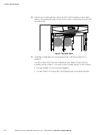
Page 18: ...utput Terminal Block L1 L2 L3 N N Remote DC battery DC DC Maintenance Bypass Auxiliary Contacts TB4 Ground TB4 Figure 6 UPS Terminal Block NOTE The two input neutral terminals are jumpered together us...

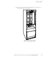
Page 19: ...llation Guide S 164201630 Rev D www eaton com powerquality 13 19 Hardwire the output terminations from the UPS to the Tie Cabinet see Figure 7 20 Repeat Steps 11 through 19 for each UPS Neutral Ground...

Page 20: ...e Cabinet 20 30 kVA Installation Guide S 164201630 Rev D www eaton com powerquality 14 21 Hardwire the load to the Tie Cabinet see Figure 8 Neutral Line 1 Ground Line 2 Line 3 Maintenance Bypass Wirin...

Page 21: ...on DO NOT use the blue wire it is normally closed NOTE There are two sets of maintenance bypass wires you can terminate to either set If you are installing four UPSs it is recommended to terminate two...

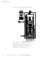
Page 22: ...Wire the AC input to the bypass breaker see Figure 10 Line 1 Line 2 Line 3 Figure 10 Bypass AC Input Wiring 26 Verify the phase rotation for each UPS and the bypass input 27 Reinstall the internal co...

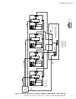
Page 23: ...TALLATION Eaton 9355 Tie Cabinet 20 30 kVA Installation Guide S 164201630 Rev D www eaton com powerquality 17 Figure 11 Parallel UPS System with Tie Cabinet Diagram Single Feed 208V or 220V Input 208V...

Page 24: ...TIE CABINET INSTALLATION Eaton 9355 Tie Cabinet 20 30 kVA Installation Guide S 164201630 Rev D www eaton com powerquality 18...

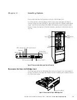
Page 25: ...location of the communication options and control terminals on the UPS DB 9 Communication Port REPO normally open Signal Input 2 Signal Input 1 X Slot Communication Bay 2 X Slot Communication Bay 1 Re...

Page 26: ...e Powerware Hot Sync CAN Bridge Card 1 Remove the UPS front door 2 Remove the communication wiring access plate from the UPS rear panel and punch a hole in it using a Greenlee punch or similar device...

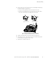
Page 27: ...Pins 1 and 2 S For three or four paralleled UPSs set the cards of the first and last UPSs to Pins 1 and 2 set the cards for the middle UPSs to Pins 2 and 3 Jumper J7 Pins 1 and 2 Jumper J7 Pins 2 and...

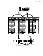
Page 28: ...X Slot communication bays on each UPS see Figure 16 Figure 16 Routing the Cables 9 Install the CAN Bridge Card wiring between each UPS see Figure 18 on page 25 Use three wires of the four wire twisted...

Page 29: ...0 30 kVA Installation Guide S 164201630 Rev D www eaton com powerquality 23 10 Route the pull chain wiring through the middle of the fan section and secure in the cable clips for each UPS see Figure 1...

Page 30: ...ct Pull Chain Output Contact Pin 2 to Signal Input 2 Pin 2 on each UPS CAUTION If polarity or wiring is not correct the parallel system does not operate normally For example when shutting down one UPS...

Page 31: ...RM 1 ALARM 2 BPO RS232 RELAY OUTPUT PULLCHAIN OUTP PARALLELONLY X27 X57 X43 X NP X52 NC X45 X44 ALARM 1 ALARM 2 BPO RS232 RELAY OUTPUT PULLCHAIN OUTP PARALLELONLY X27 X57 X43 X NP X52 NC X45 X44 SHIEL...

Page 32: ...INSTALLING OPTIONS Eaton 9355 Tie Cabinet 20 30 kVA Installation Guide S 164201630 Rev D www eaton com powerquality 26...

Page 33: ...lowing telephone numbers and ask for a UPS technical representative United States 1 800 843 9433 or 1 919 870 3028 Canada 1 800 461 9166 ext 260 All other countries Call your local service representat...

Page 34: ...SERVICE AND SUPPORT Eaton 9355 Tie Cabinet 20 30 kVA Installation Guide S 164201630 Rev D www eaton com powerquality 28...

Page 35: ...WARRANTY DOES NOT COVER This Warranty does not cover any defects or damages caused by a failure to properly store the Product before installation including the trickle charge of batteries no later th...

Page 36: ...corrective maintenance is required Any costs for replacement equipment installation materials freight charges travel expenses or labor of Eaton representatives outside the terms of this Warranty will...

Reviews: