v
EATON
Powerware
®
9390 IAC-B and IAC-T Installation and Operation Manual
S
164201590 Rev C
powerware.com
List of Figures
Figure 1-1. Powerware 9390 IAC
1-2
. . . . . . . . . . . . . . . . . . . . . . . . . . . . . . . . . . . . . . . . . . . . . . . . . . . . . . . .
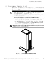
Figure 2-1. Powerware 9390 IAC as Shipped on Pallet
2-3
. . . . . . . . . . . . . . . . . . . . . . . . . . . . . . . . . . . . . .
Figure 3-1. Removing the Front Shipping Bracket on the Powerware 9390 IAC
3-3
. . . . . . . . . . . . . . . . .
Figure 3-2. Removing the Rear Shipping Bracket on the Powerware 9390 IAC
3-4
. . . . . . . . . . . . . . . . .
Figure 3-3. 40–80 kVA UPS with Line-up-and-Match IAC
3-5
. . . . . . . . . . . . . . . . . . . . . . . . . . . . . . . . . . .
Figure 3-4. 100–160 kVA UPS with Line-up-and-Match IAC
3-6
. . . . . . . . . . . . . . . . . . . . . . . . . . . . . . . . .
Figure 3-5. 40–80 kVA UPS to IAC Joining Brackets
3-8
. . . . . . . . . . . . . . . . . . . . . . . . . . . . . . . . . . . . . . . .
Figure 3-6. 100–160 kVA UPS to IAC Joining Brackets
3-9
. . . . . . . . . . . . . . . . . . . . . . . . . . . . . . . . . . . . . .
Figure 3-7. 40–80 kVA UPS with Standalone IAC
3-12
. . . . . . . . . . . . . . . . . . . . . . . . . . . . . . . . . . . . . . . . . .
Figure 3-8. 100–160 kVA UPS with Standalone IAC
3-13
. . . . . . . . . . . . . . . . . . . . . . . . . . . . . . . . . . . . . . . .
Figure 3-9. Two 40–80 kVA UPMs with Line-up-and-Match IAC
3-17
. . . . . . . . . . . . . . . . . . . . . . . . . . . . . .
Figure 3-10. Two 100–160 kVA UPMs with Line-up-and-Match IAC
3-18
. . . . . . . . . . . . . . . . . . . . . . . . . .
Figure 3-11. 40–80 kVA UPM 1 to IAC Joining Brackets
3-20
. . . . . . . . . . . . . . . . . . . . . . . . . . . . . . . . . . . .
Figure 3-12. IAC to 40–80 kVA UPM 2 Joining Brackets
3-21
. . . . . . . . . . . . . . . . . . . . . . . . . . . . . . . . . . . .
Figure 3-13. 100–160 kVA UPM 1 to IAC Joining Brackets
3-22
. . . . . . . . . . . . . . . . . . . . . . . . . . . . . . . . . .
Figure 3-14. IAC to 100–160 kVA UPM 2 Joining Brackets
3-23
. . . . . . . . . . . . . . . . . . . . . . . . . . . . . . . . . .
Figure 3-15. Two 40–80 kVA UPMs with Standalone IAC
3-26
. . . . . . . . . . . . . . . . . . . . . . . . . . . . . . . . . . .
Figure 3-16. Two 100–160 kVA UPMs with Standalone IAC
3-27
. . . . . . . . . . . . . . . . . . . . . . . . . . . . . . . . .
Figure 4-1. Path of Current Through the IAC in UPS Mode
4-1
. . . . . . . . . . . . . . . . . . . . . . . . . . . . . . . . .
Figure 4-2. Path of Current Through the IAC in Maintenance Bypass Mode
4-2
. . . . . . . . . . . . . . . . . . . .
Figure 4-3. Path of Current Through the IAC during Redundant Operation
4-3
. . . . . . . . . . . . . . . . . . . .
Figure 4-4. Path of Current Through the IAC during Redundant Operation in UPS Mode
4-4
. . . . . . . .
Figure 4-5. Path of Current Through the IAC during Redundant Operation in Bypass Mode
4-5
. . . . . .
Figure 5-1. Powerware 9390 IAC MBP and MIS Controls
5-5
. . . . . . . . . . . . . . . . . . . . . . . . . . . . . . . . . . . .
Figure 5-2. Powerware 9390 IAC MBP, MIS, BIB, and RIB Controls
5-6
. . . . . . . . . . . . . . . . . . . . . . . . . . . .
Figure 5-3. Powerware 9390 IAC MOB 1, MOB 2, and SLB Controls
5-7
. . . . . . . . . . . . . . . . . . . . . . . . . .
Figure 5-4. Powerware 9390 IAC MOB 1, MOB 2, MBP, and MIS Controls
5-8
. . . . . . . . . . . . . . . . . . . . .
Summary of Contents for Powerware 9390 IAC-B
Page 145: ......
Page 146: ...164201590C 164201590 C...


