INSTALLATION
Eaton 9390 UPS, 9395 UPS, and 9395 SSBM Sync Control Installation and Operation Manual
S
P-164000052 Rev 2
3-9
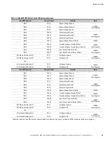
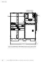
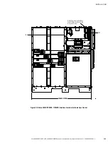
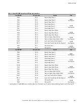
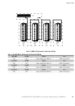
Table 3‐2. Eaton 9395 UPS System Control Wiring Interconnections
From UPS System-A
To Sync Control
Function
Note
TB6-1
TB1-4
Bypass Voltage Phase A
14 AWG
Twist Together
TB6-2
TB1-5
Bypass Voltage Phase B
TB6-3
TB1-6
Bypass Voltage Neutral
TB6-4
TB1-13
Output Voltage Phase A
14 AWG
Twist Together
TB6-5
TB1-14
Output Voltage Phase B
TB6-6
TB1-15
Output Voltage Neutral
TB6-9
TB1-17
Bypass Voltage Phase B Return
14 AWG
TB3-1
TB1-22
Transfer to Bypass Disable (24 Vdc)
14 AWG
Twist Together
TB3-2
TB1-23
Transfer to Bypass Disable Return (24 Vdc)
TB3-3
TB1-26
Sync Control Trouble (24 Vdc)
14 AWG
Twist Together
TB3-4
TB1-27
Sync Control Trouble Return (24 Vdc)
TB-4 (Relay Interface Card)*
TB1-1
On Bypass Common
14 AWG
Twist Together
TB-6 (Relay Interface Card)*
TB1-2
On Bypass NO
OR
J2-5 (Industrial Relay Card)*
TB1-1
On Bypass Common
14 AWG
Twist Together
J2-6 (Industrial Relay Card)*
TB1-2
On Bypass NO
From UPS System-B
To Sync Control
Function
Note
TB6-1
TB1-10
Bypass Voltage Phase A
14 AWG
Twist Together
TB6-2
TB1-11
Bypass Voltage Phase B
TB6-3
TB1-12
Bypass Voltage Neutral
TB6-4
TB1-7
Output Voltage Phase A
14 AWG
Twist Together
TB6-5
TB1-8
Output Voltage Phase B
TB6-6
TB1-9
Output Voltage Neutral
TB6-9
TB1-20
Bypass Voltage Phase B Return
14 AWG
TB3-1
TB1-24
Transfer to Bypass Disable (24 Vdc)
14 AWG
Twist Together
TB3-2
TB1-25
Transfer to Bypass Disable Return (24 Vdc)
TB3-3
TB1-28
Sync Control Trouble (24 Vdc)
14 AWG
Twist Together
TB3-4
TB1-29
Sync Control Trouble Return (24 Vdc)
TB-4 (Relay Interface Card)*
TB1-1
On Bypass Common
14 AWG
Twist Together
TB-6 (Relay Interface Card)*
TB1-3
On Bypass NO
OR
J2-5 (Industrial Relay Card)*
TB1-1
On Bypass Common
14 AWG
Twist Together
J2-6 (Industrial Relay Card)*
TB1-3
On Bypass NO
* Both relay Interface card (RIC) and the Industrial Relay Card (IRC) shall be set up / verified for RMP by the Eaton Field Service Engineer.


