INSTALLATION
Eaton 9910 UPS and EBM Installation Guide (6000 VA Models)
S
P-164000007 Rev 1
30
3.
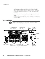
Connect the switch or circuit to the REPO connector on the rear of
the UPS using insulated size 18–20 AWG (0.75 mm
2
– 0.5 mm
2
)
wire.
Table 11. REPO Connections
Wire Function
Terminal Wire Size Rating
Suggested Wire Size
REPO
L1
4–0.32 mm
2
(12–22 AWG)
0.82 mm
2
(18 AWG)
L2
NOTE
A separate contact must simultaneously cause UPS input AC power to be removed.
4.
The REPO contacts are closed by default and cannot be changed.
The pins must be kept closed to keep the UPS running. If the UPS
shuts down because the REPO connector pins are opened, restart
the UPS by shorting the REPO connector pins and turning on the
UPS manually. Maximum resistance in the shorted loop is 10 ohm.
5.
Verify that the externally connected REPO switch is not activated.
An activated REPO switch disables power to the UPS receptacles.
NOTE
To avoid accidental load loss, always test the REPO function before you apply your
critical load.


