INSTALLATION
EATON
Powerware
®
BladeUPS
®
(12 kVA) User's Guide
S
164201649 Rev 3
www.powerware.com
54
11.
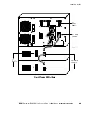
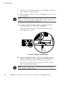
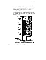
Install a redundant signal cable between the For Parallel Use Only
and Standalone/Parallel terminals on each UPS as shown in
Figure 36. Remove the existing terminal block connectors before
installing the cable.
Be sure to check correct polarity when installing the cable.
C A U T I O N
If polarity or wiring is not correct, the parallel system does not operate normally. For
example, when shutting down one UPS, the remaining UPS transfers the load to bypass
instead of supporting the load. Verify all wiring is correct for proper operation.
12.
Remove the Standalone/Parallel terminal block connector from the
last UPS (UPS 3 in Figure 36).
13.
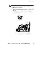
Tighten the screws securing each Powerware Hot Sync CAN Bridge
Card in its X-Slot communication bay.
14.
If you are installing power management software, connect your
computer to the UPS communication port or optional X-Slot card
(see page 89). For the communication port, use the supplied serial
cable.
NOTE
You may install one ConnectUPS -X Web/SNMP Card per UPS, or one card per
parallel system. Installing one card per UPS provides communication with each UPS.
Installing one card per parallel system provides detection of a problem with at least one UPS,
but does not specify which UPS or how many.
15.
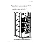
If you left the UPSs unattached to the rack, secure the front and
rear of each UPS as described in Steps 14 and 15 on page 40.
16.
If your rack has conductors for grounding or bonding of ungrounded
metal parts, connect the ground cable (not included) to the ground
bonding screw. See Figure 32 on page 49 for the location of the
ground bonding screw.
17.
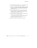
You can install an optional REPO circuit that will shut down the
entire parallel system using a single switch. See “Remote
Emergency Power-off” on page 95 to install the REPO switch
before powering on the parallel system.
t

