INSTALLATION
EATON
Powerware
®
BladeUPS
®
(12 kVA) User's Guide
S
164201649 Rev 3
www.powerware.com
62
6.
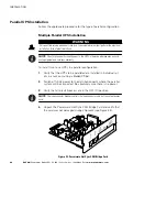
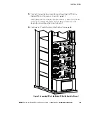
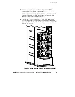
Loosely install the Powerware Hot Sync CAN Bridge Card into the
open X-Slot on the UPS rear panel.
7.
Repeat Steps 3 through 6 to install a CAN Bridge Card in each
newly installed UPS to be paralleled.
8.
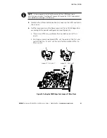
Repeat Steps 4 through 6 to reset the jumper pins in each
previously installed UPS to be paralleled. Depending on
configuration, not all previously installed UPSs may need their
jumper pins reset.
In a parallel system not previously shut down, the system will
report various alarms until the CAN Bridge Cards are fully installed
and connected.
NOTE
The BladeUPS parallel system can automatically assign identities to each UPS in the
system based on the order in which their CAN Bridge Cards are wired in Steps 9 and 10. For
more information, see “Auto-Identification” on page 99.
9.
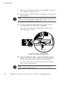
Verify that the supplied initializing jumper is installed in the CAN IN
port on the first UPS (UPS 1 in Figure 43).
On startup, the parallel system will identify the UPS with the
initializing jumper as UNIT 1.
10.
Using the supplied connectors, install a CAN Bridge Card cable
between each UPS as shown in Figure 43, connecting the CAN
OUT port on one UPS to the CAN IN port on the next UPS.
On startup, the parallel system will identify the UPS wired after
UNIT 1 as UNIT 2, and so forth.
NOTE
You can configure the parallel system with UPS 1 at the bottom of the rack (as
shown in Figure 43) or at the top of the rack.
11.
For a parallel system not previously shut down, verify that any
alarms related to reconfiguring the CAN Bridge Cards have cleared.

