FIELD INSTALLED UPM INSTALLATION
EATON
9395 Field Installed UPM Mechanical Installation Manual
S
164201717 Rev 3
www.eaton.com/powerquality
4−3
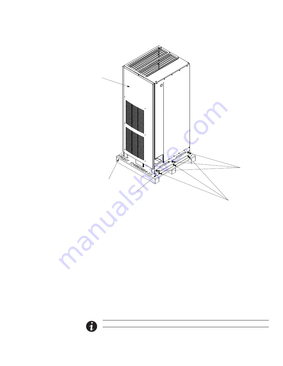
Shipping Bracket
Bolts
Shipping Bracket
Bolts
Pallet
Right Side Shipping
Bracket
FI−UPM Removable
Front Panel
Figure 4-2. Removing the Right Side Shipping Bracket
4.3
Mechanical Installation
To mechanically install the FI−UPM:
1.
Remove the wire entry plate located on the bottom left side of the UPS cabinet
(see Figure 4-3).
2.
If not already removed, remove the wire entry knockout located on the top left
side of the UPS cabinet (see Figure 4-3).
3.
Locate the hardware kit (packed inside of the cabinet). Locate the nylon grommet
from the hardware kit. If not already installed, install the nylon grommet in the
knockout hole.
4.
Using a forklift, move the FI−UPM cabinet to the final installed location on the left
side of the UPS cabinet. Verify that the FI−UPM cabinet right side is against the
UPS cabinet left side and the front panels are flush with each other.
5.
Carefully lower the FI−UPM cabinet until the cabinet base contacts the floor.
NOTE
A flat cabinet joining bracket is provided for securing the cabinets at the top front (see Step 7).
6.
Remove and retain one top screw and two bottom screws securing the FI−UPM
front panel (see Figure 4-2). Lift the panel straight up to remove it from the panel
hanger bracket at the top of the cabinet.


