2 Engineering
2.7 Braking resistances
DC1-S…20…, DC1-S…OE1 Variable Frequency Drives
05/21 MN040058EN
www.eaton.com
37
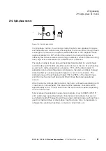
Figure 12: Braking cycle, fast motor stop with external brake resistor
Selecting brake resistors
Brake resistors are selected based on continuous power dissipation P
DB
and
maximum peak pulse power P
Peak
. The brake resistor must be adequate for
both powers.
The maximum pulse power is defined by the braking torque – kinetic energy
W
kin
during braking – that is fed back by the motor during braking.
A simplified method that can be used is to take the variable frequency drive’s
braking power P
max
or the rated motor output and use it as peak pulse power
P
Peak
for sizing purposes, since the mechanical braking power will be
reduced by the motor’s and inverter’s efficiency.
The required rated power / continuous rating for braking resistance P
DB
is
calculated using braking energy W
kin
and cycle time t
C
:
If the kinetic energy is not known, you will need the ratio of braking time
t
Braking
to cycle time t
C
:
The required continuous rating for a duty factor of 10 % (= DF[%]), for
example, can be calculated as follows:
This means that the brake resistor’s continuous rating P
DB
will always be
lower than maximum pulse power P
Peak
by the DF[%] factor.
Resistance R
B
must be at least as high as the breaking transistor’s minimum
permissible resistance R
min
.
M
Motor
Mains
R
B
BR
DC+
=
~
~
=
U
DC
n
t
P
P
RD
P
PEAK
t
t
Brems
t
OFF
t
Brems
t
C
P
Peak
∼
P
max
=
1
x
W
kin
2
t
Brems
P
DB
=
W
kin
t
C
DF [%] =
t
Brems
x 100 %
t
C
P
DB
= P
Peak
x 10 %
→
Use brake resistors with the recommended R
Brec
resistance
values for the DC1-S… variable frequency drives’ ratings.
→
For the rated braking resistances for DC1-S… variable frequency
drives, please refer to
Summary of Contents for PowerXL
Page 4: ......


