80 kVA - 130 kVA UPS
User’s and Installation Manual
1017397
Revision D (update)
13
Table 1.
The UPS floor loading of UPS modules SPM 9340 modules and battery cabinets.
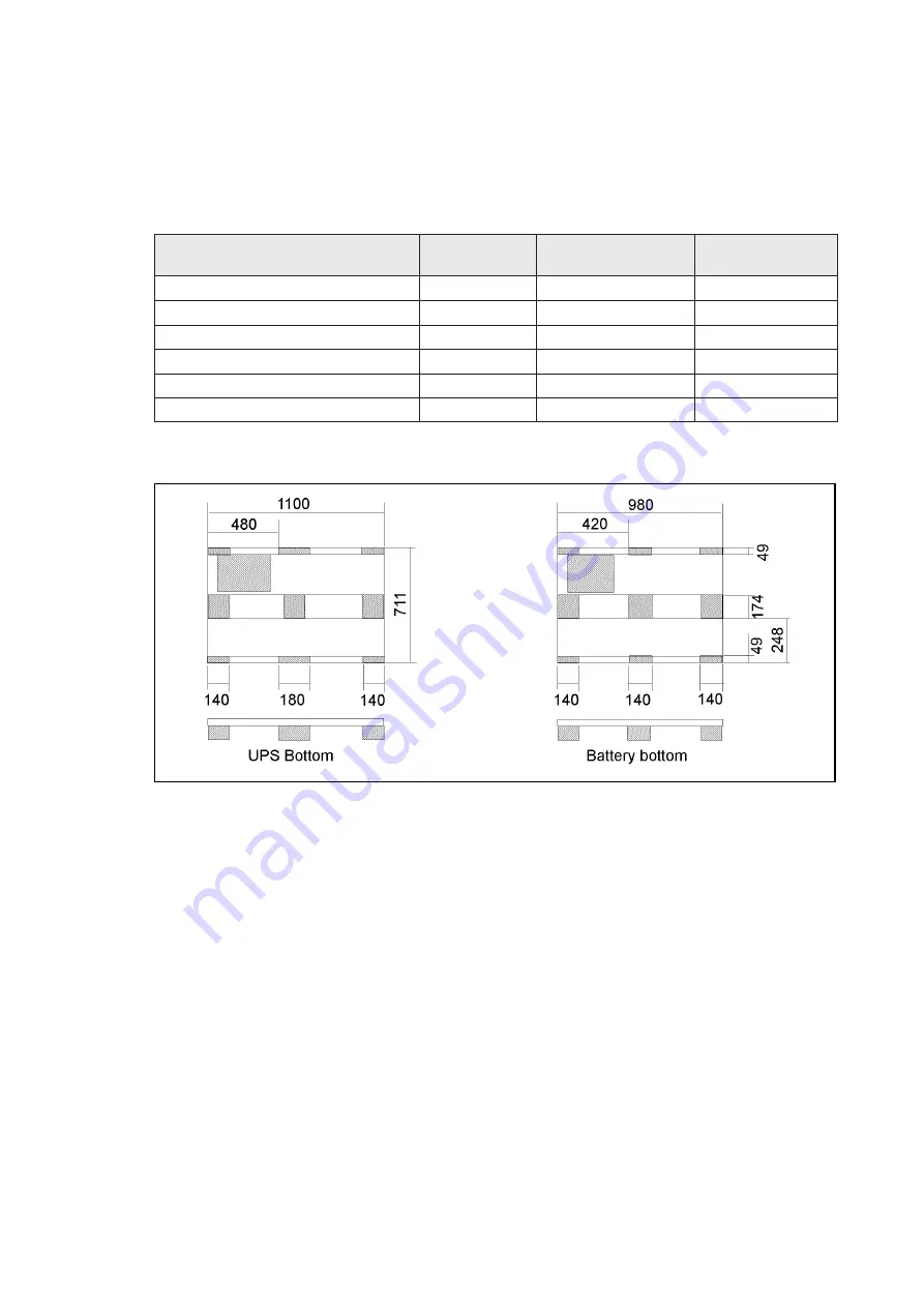
Figure 4b.
Bottom view of UPS and battery cabinets (view angle is from below).
5.3 Installing UPS and battery system
The battery cabinets may be installed on either side of the UPS or in a separate place.
When connecting UPS and battery cabinets together the side plate of the UPS has to be
removed. Removed UPS side plate shall be installed to the last battery cabinet in string.
The battery cabinets are delivered with sheet metal plates to be installed between the
UPS and battery cabinets, see figure 5.
Note!
Battery cabinets and racks made from metal must be either connected to the protective
conductor or insulated from the battery and the place of installation (EN 50272-2).
5.2 Floor loading
When planning the installation the floor loading must be taken into consideration
because of the heavy weight of the UPS and battery cabinets.
The strength of the installation surface must be adequate for point and distributed
loadings given in table 1.
n
o
i
t
p
i
r
c
s
e
D
t
h
g
i
e
W
)
g
k
(
g
n
i
d
a
o
l
t
n
i
o
P
m
c
/
g
k
(
2
)
d
e
t
u
b
i
r
t
s
i
D
m
/
g
k
(
g
n
i
d
a
o
l
2
)
A
V
k
0
3
1
-
0
8
/
s
e
l
u
d
o
m
S
P
U
/
0
4
0
1
/
9
8
.
0
/
4
3
2
1
e
l
u
d
o
m
0
4
3
9
M
P
S
0
1
3
8
2
.
0
2
8
3
t
e
n
i
b
a
c
y
r
e
t
t
a
B
0
5
2
R
H
T
A
B
0
5
0
1
2
9
.
0
8
3
4
1
t
e
n
i
b
a
c
y
r
e
t
t
a
B
5
0
3
R
H
T
A
B
0
0
2
1
5
0
.
1
4
4
6
1
t
e
n
i
b
a
c
y
r
e
t
t
a
B
0
5
3
R
H
T
A
B
0
5
3
1
8
1
.
1
9
4
8
1
t
e
n
i
b
a
c
y
r
e
t
t
a
B
5
7
4
D
C
T
A
B
0
0
8
1
8
5
.
1
5
6
4
2


