80 kVA - 130 kVA UPS
User’s and Installation Manual
1017397
Revision D (update)
19
Mains and load connections
The proper connection order is as follows:
1.
Switch off the supply to the distribution point to which the UPS unit is to be
connected.
2.
For extra safety, also remove the fuses from the selected lines
.
Make absolutely sure with measurement that there is no power.
3.
A readily accessible disconnect device must be incorporated in all fixed input
wiring. The disconnect device shall have a contact separation of at least 3 mm.
Since the SCR model does not have automatic backfeed isolation a warning label
must be added on all primary power isolators installed remote from the UPS area
to warn electrical maintenance personnel.
The warning label shall carry the following wording or equivalent:
ISOLATE UNINTERRUPTIBLE POWER SYSTEM (UPS) BEFORE WORKING ON
THIS CIRCUIT.
4.
Check that electrical connections to the installation site have been properly
executed. Also check fuse or circuit breaker ratings and cable dimensions against
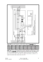
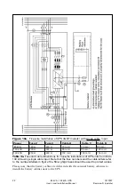
tables 3 or 4 for 80-130 kVA systems. The figure to follow depends on use of two-
cable or single-cable input.
5.
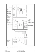
The UPS should be connected in accordance with figures 9 and 10.
6.
If one cable installation is considered, the interconnection cables provided with
UPS shall be connected between rectifier and bypass input terminals. The
interconnection cables are labelled L1, L2, L3.
7.
Connect input cables and output cables to the UPS.
If load requires using of neutral wire, a neutral connection to bypass input shall
be provided.
8.
Make sure that the UPS unit output cable is connected to the load.
9.
Also connect any computer and alarm connections according chapter 6.
These connections are in the user interface area behind the right-hand door.
10.
If an external bypass switch will be used, contact your dealer first.
The UPS unit is now connected to the mains and to the load but there is no power.
Make sure that the connections are properly made.


