80 kVA - 130 kVA UPS
User’s and Installation Manual
1017397
Revision D (update)
26
6.4 Inputs
The UPS communication device includes four inputs (terminal block 2: 1-2, 3-4, 5-6, 7-
8) for building alarms. These inputs can be for example informing when UPS gets
power from generator, shutting down and starting up inverter remotely or turning to
bypass mode remotely. These inputs can be activated by connecting the two pins
together of the particular terminal.
These inputs have the following values:
Generator On Input TB2:1,2
The generator on input is used for inhibiting the transfer to static bypass line when the
UPS is supplied by an unstable ac source.
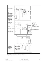
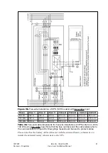
The generator auxiliary contact wires are connected on terminal block 2: 1,2 (see figure
11). In normal operations the terminals 1 and 2 are not be connected together. When
these pins are connected together by floating contacts of the generator control device,
the logic circuitry in the UPS will prevent the transfer to unstable power source. When
the unit is delivered the connection on terminals 1 and 2 will be open.
Remote Output On/Off Input TB2: 3, 4
The remote output on/off input is used to turn off the output of the UPS from a distance.
Remote output on/off wires are connected on terminals 3 and 4 (see figure 11).
The terminals 3 and 4 are not to be connected together in normal operation. When the
pins are connected together by floating contact the inverter will be turned off and also the
static bypass line will be turned off. In order to turn on the inverter and the static bypass
line the connection between these pins have to be opened.
External Bypass Switch Input TB2: 5, 6
If the UPS system is equipped with an external bypass switch, its status can be monitored
by the UPS via terminals 5 and 6. The external bypass switch auxiliary contact wires are
connected on terminals 5 and 6 (see figure 11). For normal UPS operation the connection
shall be open as default. If an external bypass switch will be used, contact your dealer first.
Environment Alarm Input TB2: 7, 8
The environment alarm input is used for connecting the UPS to your building alarms,
such as overtemperature or smoke detector alarms.
The environment alarm input contact wires are connected on terminals 7 and 8 (see
figure 11). When this alarm is activated it will be indicated to the user through RS232
ports. When connection in terminals 7,8 is open, the alarm is inactive as default.
Note!
The programmable auxiliary inputs (Generator ON, External Bypass Switch, Remote Output
On/Off, Environment Alarm) must not be galvanically connected to any mains connected
circuits. Reinforced insulation to the mains is required for equipments and cables connected
to these connections.
Note!
The programmable auxiliary inputs are NOT galvanically isolated from each other. Use
dry contacts.
6.5 X-Slot Modules
Optional X-Slot modules allow the UPS to communicate in a variety of networking
environments and with different types of devices. The Powerware 9340 is compatible
with any X-slot module, including:
•
RS232 Module - has one serial communication port.
•
Modbus/Jbus Module - connects to an industrial automation system
•
AS400 Relay Module - provides additional relay outputs
•
SNMP/Web Module - has a flexible SNMP/Web communication port.
•
Modem Module - provides modem functions for remote monitoring


