80 kVA - 130 kVA UPS
User’s and Installation Manual
1017397
Revision D (update)
37
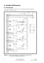
System communication with a CANBUS interface
A 10-meter CANBUS interconnection cable with termination resistors (2*120 ohm) are
supplied for parallel UPS modules. The CANBUS cable must be connected between the
TB4 terminals of two successive UPS modules as shown in the earlier wiring diagram of
parallel UPS system. A shielded, twisted pair cable with maximum length of 40 meters
must be used.
The CANBUS is a linear communication interface. It must not form a loop
configuration. Intermediate termination resistors are removed in parallel systems of 3-4
UPS modules. Only the first and last UPS modules in the CANBUS chain must have a
termination resistor fitted in cable end connected to TB4 terminals pin 1 ‘CANH’ and
pin 2 ‘CANL’.
Figure 15.
TB4 communication terminals of UPS modules and CAN cable with
resistors.
Note!
Pay attention to the signal polarity because pins 1 ‘CANH’ and pin 2 ‘CANL’ must not
be interchanged between UPS modules. The shield is connected to pin 3 ‘COMMON’ on
the TB4 terminal from both ends.
Hot Sync
™
communication with a 6-pin parallel interface
In addition to the CANBUS cable, a 6-pin parallel intercommunication cable (10-
meters) is supplied with parallel UPS modules. The cable forms a redundant
communication interface between successive ‘A18’ communication boards of UPS
modules.
The ‘A18’ communication boards have parallel terminals X3 and X4. The 6-pin parallel
cable must be connected between these two terminals of UPS modules. It’s
recommended that the cabling form a loop configuration to increase redundancy level
of parallel communication. The shield of each parallel intercommunication cable must
be connected to PE from one of the cable ends. The PE connection is located next to
the ‘A18A communiction board in the frame of UPS cubible.
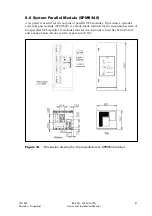
Figure 16.
X3 and X4 communication terminals in the ‘A18’ communication board.


