background image

14

Internal Battery Instructions for the Eaton 9355 UPS (20/30 kVA)

164201708—Rev 03

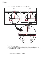
Figure 11. Connecting the Cabinet Wiring Harness to Battery Tray Wires

Red            Black

Wire       Wire

Black       Black

Red 

     Red

White Wire

Red 

       Red

Black         Black

Cabinet

Wiring

Harness

Battery Tray

Wiring

Battery Tray

Wiring

TB2


+

TB2


+

19. Reinstall the battery cover panel.

20. Refer to the

Eaton 9355 UPS (20/30 kVA) Installation and Operation Manual

to continue installing the UPS.

Otherwise, reinstall the UPS front door.

Installation

Summary of Contents for PWHR1234W2FR

Page 1: ...p n 164201708 Revision 03 For use with the Eaton 9355 20 30kVA UPS Eaton Internal Battery Instructions ...

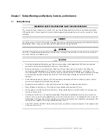
Page 2: ...may be reproduced in any way without the express written approval of Eaton IMPORTANT SAFETY INSTRUCTIONS SAVE THESE INSTRUCTIONS This manual contains important instructions that you should follow during installation and maintenance of the UPS and batteries Please read all instructions before operating the equipment and save this manual for future reference CONSIGNES DE SÉCURITÉ IMPORTANTES CONSERV...

Page 3: ... gs s a an nd d S Sy ym mb bo olls s C Co on nt tr ro olls s a an nd d I In nd diic ca at to or rs s 1 1 1 1 Safety Warnings 1 1 2 Consignes de Sécurité 2 1 3 Advertencias de Seguridad 3 1 4 Symbols Controls and Indicators 4 2 2 I In ns st ta alllla at tiio on n 5 5 2 1 Battery Type 5 2 2 Removing and Replacing the UPS Front Door 5 2 3 Installing the Internal Batteries 6 ...

Page 4: ...iv Internal Battery Instructions for the Eaton 9355 UPS 20 30 kVA 164201708 Rev 03 Table of Contents ...

Page 5: ...cal shock or burn from high short circuit current The following precautions should be observed 1 Remove watches rings or other metal objects 2 Use tools with insulated handles 3 Do not lay tools or metal parts on top of batteries 4 Disconnect charging source prior to connecting or disconnecting battery terminals 5 Wear voltage rated gloves and electrical hazard footwear When replacing batteries re...

Page 6: ...batteries Les batteries peuvent présenter un risque de choc électrique ou de brûlure provenant d un courant de court circuit haute intensité Les précautions suivantes doivent être observées 1 Retirez montre bagues ou autres objets métalliques 2 Utilisez des outils aux poignées isolantes 3 Ne déposez pas d outils ou de pièces métalliques sur les batteries 4 Déconnectez la source de chargement avant...

Page 7: ...rías Las baterías pueden constituir un riesgo de descarga eléctrica o quemaduras por corriente alta de corto circuito Debe tomar las siguientes precauciones 1 Quítese el reloj los anillos u otros objetos de metal 2 Utilice herramientas con manijas aisladas 3 No coloque las herramientas o piezas de metal en la parte superior de las baterías 4 Desconecte la fuente de carga antes de conectar o descon...

Page 8: ...efer to your operator s manual for additional information such as important operating and maintenance instructions Special Symbols The following are examples of symbols used on the UPS or accessories to alert you to important information RISK OF ELECTRIC SHOCK Observe the warning associated with the risk of electric shock symbol CAUTION REFER TO OPERATOR S MANUAL Refer to your operator s manual fo...

Page 9: ...anufactures Types and Quantity Battery Manufacturer Eaton CSB Battery Co Ltd EnerSys Inc GS Yuasa Corporation Japan Storage Battery Type PWHR1234W2FR HRL1234WFR NPX L35 250TW NPX 35 or NPX 35FR PX12090F2 PX12090 or PE12V7 2 Battery Quantity 18 per string 18 per string 18 per string 18 per string 2 2 2 2 R Re em mo ov viin ng g a an nd d R Re ep plla ac ciin ng g t th he e U UP PS S F Fr ro on nt t...

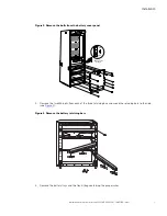
Page 10: ... g t th he e I In nt te er rn na all B Ba at tt te er riie es s WARNING Ensure all External Battery Cabinets EBC are disconnected from the UPS To install the internal batteries 1 Verify that the UPS battery circuit breaker is in the OFF position see Figure 2 2 Remove the 13 M5 bolts from the battery cover panel and remove the panel Installation ...

Page 11: ... from the battery cover panel ON OFF Battery Circuit Breaker 3 Remove the two M5 bolts from each of the three retaining bars and move the retaining bars to the side see Figure 3 Figure 3 Remove the battery retaining bars 4 Remove the battery trays and the tray kit bag containing the jumper wires Installation ...

Page 12: ...ord the oldest date code from that string of batteries Date code information will be needed for later use see Step 14 6 Insert the nine batteries into a battery tray as shown in Figure 5 Place the batteries with the connectors at the bottom Figure 5 Batteries in Tray Back of Tray Front of Tray 7 Connect eight jumper wires between the batteries Installation ...

Page 13: ...tray wire harness see Figure 6 to the positive battery terminal at the front of the tray then run the rest of the wire to the back of the tray for later use see Figure 7 for more detail Figure 6 Battery Tray Wire Harness Red Wire Black Wire 9 Connect the long black wire of the battery tray harness to the negative battery terminal at the back of the tray 10 Tie wrap the wires to the jumper wires in...

Page 14: ...ke sure the sides of the battery tray are bent upward 12 Place the battery tray top over the batteries see Figure 8 NOTE You may need to place something heavy on the top while taping the battery tray 13 Wrap the supplied tape around the batteries securing the top and bottom trays to the batteries Verify that the bent sides of the trays are secure under the tape see Figure 8 Installation ...

Page 15: ...9355 UPS 20 30 kVA 164201708 Rev 03 11 Figure 8 Securing the Top and Bottom Battery trays Back of Tray Front of Tray Battery Tray Top Tape 14 Write the oldest date code from the battery string from Step 5 on the top tray see Figure 9 Installation ...

Page 16: ...ry String Oldest Date Code Front of Tray 2021 12 Date Code Year YYYY Month MM example December 2021 2021 12 15 Repeat Step 5 through Step 15 for each battery tray 16 Load four battery trays into the bottom of the cabinet see Figure 10 Repeat for the middle and top rows of battery trays Installation ...

Page 17: ... 13 Figure 10 Installing the battery trays 17 Reinstall the battery retaining bars 18 Connect the factory installed cabinet wiring harness to the battery tray wiring harnesses beginning from the top left as shown in Figure 11 Repeat for the other rows of battery trays Installation ...

Page 18: ...ay Wires Red Black Wire Wire Black Black Red Red White Wire Red Red Black Black Cabinet Wiring Harness Battery Tray Wiring Battery Tray Wiring TB2 TB2 19 Reinstall the battery cover panel 20 Refer to the Eaton 9355 UPS 20 30 kVA Installation and Operation Manual to continue installing the UPS Otherwise reinstall the UPS front door Installation ...

Page 19: ...Internal Battery Instructions for the Eaton 9355 UPS 20 30 kVA 164201708 Rev 03 15 Installation ...

Page 20: ...16420170803 164201708 03 ...

Reviews: