12
5 Installation
The floodlight is suitable for special operating conditions such as on
offshore platforms or in chemical or pharmaceutical plants.
The adding of further modules or the removal of modules from the modular
PXLED floodlight by the operator is not permitted.
The intended use does not include applications with
high-charging processes. Those could be for example high-voltage
sources generating ion-winds or pneumatically transported dust
atmospheres in touch with the enclosure.
X
ATEX - IEC
The floodlight has to be protected against electrostatic
discharges.
The data as per point 3 and 4 shall be taken into account with the use.
Applications other than those described are not permitted
without Cooper Crouse-Hinds’s / EATON’s prior written consent.
The instructions stated in section 7 of the operating instructions
shall be observed during operation.
The user alone is responsible for the appropriate use of this
junction box in consideration of the basic conditions existing at the
plant (see technical data).
The product is protected by patents. For more information, please contact
your local Cooper Crouse-Hinds / EATON representative.
6 Installation
For the mounting and operation, the respective national regulations as
well as the general rules of engineering will have to be observed
(IEC/EN 60079-14).
The improper installation and operation of floodlight may result in
the explosion protection and invalidation of the guarantee.
Transport and storage only in original packaging in a closed and dry room!
Observe for any cracks or damage in housing and glass during installation
or reparation! Don´t damage the fire-finish of the glass adquired during
moulding (abrasions, sanding, etc.) that can weaken their mechanical
functions.
6.1 Montage
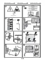
See fig. 1 ... 7
The flood lights can be mounted without opening their enclosure.
If cable entries are used from the top, mount only in dry rooms or attach
where protected from moisture.
!
For wall assembly Cable entry from below.
The flood light may rest evenly only at the respective fastening points.
Mounting surfaces, e.g. walls, ceilings or parts of frameworks, have to be
flat.
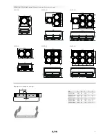
The chosen screw shall match the fastening hole (see dimensional
drawing) and it must not damage the hole (e. g. use of a washer).
If the screws are overtightened, the apparatus can be damaged.
6.2
Opening flood light connection cabinet
See fig 6
Warning against electric shock.
Ensure and take suitable precautions before opening the housing.
Warning of explosion.
Before opening the housing to make sure that no explosive atmos-
phere environment.
Additional mounting material see CCH / EATON catalogue.
6.2.1 Cable entries
The cables and cable entries must correspond with the minimum
temperature resistance depending on the lamp (see technical data).
Connecting cable exposed to strain must be relieved by suitable
measures.
When assembling the cable entries for the mains connection, please observe
the manufacturer’s specifications for the used seals and cable entries!
– Introduce the cable through the Ex cable entry.
When using plastic KLEs use
sealing inserts 1,2 and 3 for cables from 8 to 10 mm Ø,
sealing inserts 1 and 2 for cables from 10 to 13 mm Ø
and sealing insert 1 for cables from 13.5 to 17.5 mm Ø.
Pay attention to the proper fit of the remaining sealing insert in the
cable gland.
For metal KLE see additional KLE instruction.
Unused cable entries have to be closed by a correspondante certified
blanking plug.
The cable entries and sealing stoppers must be approved for the lamp’s
type of protection!
In order to ensure the required minimum protection category, the cable
glands shall be tightened down (test torque) .
Overtightening might impair the protection category.
6.2.2 Electrical connection
The electrical connection of the equipment must be performed
by qualified electricians (IEC/EN 60079-14).
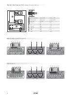
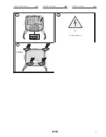
See wiring diagram and fig. 8 and 9.
All screws and/or nuts of the connection terminals, including those not in
use, shall be tightened securely.
To maintain the explosion protection, the connection of conductors
shall be carried out with special care.
The minimum and maximum conductor cross sections shall be taken
in account (see technical data).
The respective regulations shall be taken into account when connecting
the correctly stripped connection conductors of the cables.
Only carry out insulation measurements between PE and the external
conductor L1 (L, L2, L3) as well as between PE and N.
– measuring voltage: max. 1 kV DC
– measuring current: max. 10 mA
Explosion protected flood light type: PXLED
GB
Summary of Contents for PXLED
Page 18: ...18 Notizen Notes Remarques ...
Page 19: ...19 Notizen Notes Remarques ...


