background image

p/n: 164201675

Revision 02

24–96A: 208Y/120V, 400Y/230V User's Guide

Eaton Rack Power Module

Summary of Contents for RPM-3U

Page 1: ...p n 164201675 Revision 02 24 96A 208Y 120V 400Y 230V User s Guide Eaton Rack Power Module...

Page 2: ...harmonized standards and EU directives Harmonized Standards IEC 61000 3 12 EU Directives 73 23 EEC Council Directive on equipment designed for use within certain voltage limits 93 68 EEC Amending Dir...

Page 3: ...operly For more information contact your local recycling reuse or hazardous waste center This symbol indicates that you should not discard waste electrical or electronic equipment WEEE in the trash Fo...

Page 4: ......

Page 5: ...tional 6 2 6 Wallmount Installation 7 2 7 Rack Installation 8 2 8 Plug Receptacle Installation 10 2 9 Hardwired Installation 11 2 10 Advanced Metering Installation Optional 13 3 3 O Op pe er ra at tii...

Page 6: ...vi Eaton Rack Power Module 164201675 Rev 02 Table of Contents...

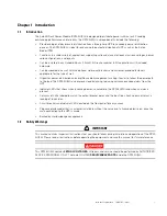
Page 7: ...stribution and simplifies cable management making it easier to follow the power path to the load The RPM 3U 3Ui also improves load balancing reducing nuisance overload alarms from the UPS Indicator LE...

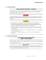
Page 8: ...ierement ces instructions avant de faire fonctionner l equipement et conserver ce manuel afin de pouvoir vous y reporter ulterieurement Cet RPM 3U 3Ui contient des TENSIONS MORTELLES Toute operation d...

Page 9: ...uchtigkeit max 95 betreiben Um internationale Normen und Verdrahtungsvorschriften zu erfullen durfen die an den Ausgang dieser RPM 3U 3Ui angeschlossenen Gerate zusammen einen Erdableitstrom von insge...

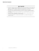
Page 10: ...5 maximo Para cumplir con los estandares internacionales y las normas de instalacion la totalidad de los equipos conectados a la salida de este RPM 3U 3Ui no debe tener una intensidad de perdida a tie...

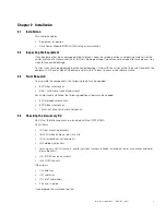
Page 11: ...thin 15 days to your service representative 2 2 3 3 T To oo olls s R Re eq qu uiir re ed d To assemble the components the following tools may be needed 2 Phillips screwdriver 5 16 nut driver or socket...

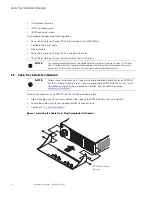
Page 12: ...on com powerxpert 2 2 5 5 C Ca ab blle e T Tr ra ay y I In ns st ta alllla at tiio on n O Op pt tiio on na all NOTE Follow these instructions only if you are installing an optional cable tray on an RP...

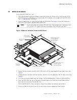
Page 13: ...ired Unit Shown M4 Flat Head Screws 4 places M4 Pan Head Screws 8 places 40 6 cm 16 50 8 cm 20 Cable Tray optional Vertical dimension for customer supplied mounting fasteners Horizontal dimension for...

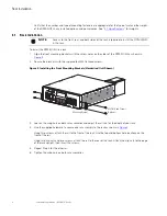
Page 14: ...3 2 Secure the brackets with the supplied four M4 flat head screws Figure 3 Installing the Front Mounting Brackets Hardwired Unit Shown M4 Flat Head Screws 4 places Mounting Bracket 3 Loosen the wing...

Page 15: ...upright until secured 8 Slide the RPM 3U 3Ui into the rack 9 Secure the front of the RPM 3U 3Ui to the rack with the supplied screws see Figure 5 10 Loosen the wing nut on each rear hold down bracket...

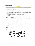
Page 16: ...2 The RPM 3U 3Ui receptacles are protected separately by each circuit breaker on the front panel Confirm that the equipment connected to the RPM 3U 3Ui does not exceed the RPM 3U 3Ui s capacity See Sp...

Page 17: ...ker rating options To hardwire the RPM 3U 3Ui 1 Verify that the RPM 3U 3Ui is properly installed in the rack or wallmount brackets and that each circuit breaker on the RPM 3U 3Ui front panel is in the...

Page 18: ...Function Terminal Position Terminal Wire Size Rating Tightening Tourqe Ground Gnd 35mm 1 AWG NOTE Refer to label on terminal block Neutral N Phase 3 L3 Phase 2 L2 Phase 1 L1 Use 90 C copper wire minim...

Page 19: ...wer Xpert Gateway Series 1000 Card shown in Figure 9 is factory installed in the X SlotR communication bay on the front of the RPM 3U 3Ui To connect the cables and configure the card 1 Locate the Powe...

Page 20: ...14 Eaton Rack Power Module 164201675 Rev 02 Advanced Metering Installation Optional...

Page 21: ...ame receptacle type or different types See 4 1 Specifications for a complete list of available output plate receptacle types Figure 10 shows an example of a rear panel Figure 10 RPM 3U 3Ui Rear Panel...

Page 22: ...ted number on the receptacles on the rear panel see The receptacles are labeled right to left matching the breakers directly connected to them The columns of LEDs in the LED display see Figure 11 are...

Page 23: ...ng A Alla ar rm m a an nd d P Po ow we er r I In nd diic ca at to or rs s The RPM 3U 3Ui has two indicators to the left of the LED display Table 2 Alarm Indicators Indicator On Off Alarm Alarm Conditi...

Page 24: ...18 Eaton Rack Power Module 164201675 Rev 02 LED Display...

Page 25: ...61 cm 5 75 Weight NOTE Weight varies depending on installed options Typical Hardwired Unit 14 5 kg 32 lb Typical Plug Receptacle Unit 13 6 kg 30 lb Typical Power Cord up to 9 1 kg 20 lb Cable Tray 0 8...

Page 26: ...al Frequency Range 50 60 Hz 45 65 Hz Input Conductor Configuration 3 wire N Gnd Input Power Factor Load dependent Input Current THD Load dependent Table 9 Electrical Input Ratings Model Input Connecti...

Page 27: ...3 2 Phase to Neutral Number of Breakers Receptacles per Breaker Breaker Rating 3 two pole breakers 1 20A 5 000 AIC Table 14 Output Plate Receptacle Type L6 30R Receptacle Voltage Number of Receptacles...

Page 28: ...Phase Neutral Number of Breakers Receptacles per Breaker Breaker Rating 2 three pole breakers 1 20A 5 000 AIC Table 20 Output Plate Receptacle Type L21 30R Receptacle Voltage Number of Receptacles Rec...

Page 29: ...2 Phase to Phase Number of Breakers Receptacles per Breaker Breaker Rating 3 two pole breakers 2 20A 5 000 AIC Table 24 Output Plate Receptacle Type IEC 320 C19 400Y 230V Receptacle Voltage Number of...

Page 30: ...5 Rev 02 Figure 13 Output Receptacle Types 5 15R 5 20R L6 15R L6 20R L6 30R L14 20R L14 30R L15 20R L15 30R IEC 320 C13 208Y 120V IEC 320 C13 400Y 230V IEC 320 C19 208Y 120V IEC 320 C19 400Y 230V R 0...

Page 31: ...Possible Cause Action Alarm indicator is illuminated Overload condition Remove some of the equipment from the RPM 3U 3Ui Alarm and Power indicators are illuminated The TVSS indicator if TVSS is instal...

Page 32: ...26 Eaton Rack Power Module 164201675 Rev 02 Service and Support...

Page 33: ...Eaton Rack Power Module 164201675 Rev 02 27 C Ch ha ap pt te er r 6 6 W Wa ar rr ra an nt ty y 6 6 1 1 W Wa ar rr ra an nt ty y Limited Factory Warranty...

Page 34: ...16420167502 164201675 02...

Reviews: