Page 6
Connection Details
TR
The TR terminal provides the control unit
with the tamper status of the siren. TR is
activated (and the siren self-activates) if
any of the following occurs:
a) The siren's tamper switch is activated.
b) The BELL input from the control
unit/expander is cut, providing the Trig
Mon link (page 7) is fitted (SDR-WEXT-
G3 only).
c) Power from the control unit/expander is
disconnected.
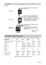
When using the SDR-WEXT-G2, TR is 0V
in normal operation, and switched to open
circuit when a tamper is detected.
When using the SDR-WEXT-G3, the
voltage and termination of the TR terminal
must be configured using the Tmp Feed
jumper (see page 8).
ENG (Installer Mode)
Setting the ENG input to 0V sets the siren
in installer (engineer) mode. You should
normally connect ENG to a control
unit/expander output configured as type
"Installer on Site", which activates when
entering the Installer menu at a keypad and
deactivates when exiting the Installer menu
(at every keypad).
Installer mode prevents the sounder and
strobe from activating when the lid is
opened.
When installer mode is activated, both
comfort LEDs switch on continuously for a
few minutes.
STR and BELL
0V at the STR (strobe) input activates the
strobe. 0V at the BELL (trigger) input
activates the sounder. Some control units
provided dedicated strobe and bell outputs.
If not (or an expander is used), connect to
outputs of type "Strobe" and "Siren"
respectively.
F-F and F-R and RST
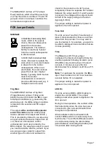
The SDR-WEXT-G3 provides F-F (Fault
Feed) and F-R (Fault Return) volt-free
terminals, which are used to provide
sounder and battery fault reporting to the
control unit.
To enable sounder and battery fault
reporting, see
on page 4
for connection and configuration details.
Technical Detail for Advanced Installers
The siren tests the battery voltage under
load conditions every hour and when the
ENG input is deactivated. The sounder is
tested each time it is activated. Under
normal conditions, F-F and F-R are closed
circuit. If either test fails, F-F and F-R go
open circuit, which causes the control unit
to generate an alarm. The contacts remain
open circuit until the test is successful or
the siren's tamper switch is activated (in the
latter case, the siren assumes that an
engineer is fixing the problem).
A sounder or battery fault may prevent the
system from being set (depending on
grade) and cannot be cleared until the
siren's tamper switch is activated, or the
test is performed again and passes.
You can start a test manually by using the
Installer Menu
– Test – Sirens & Sounders
– Wired Sirens – Remote Self-Test
, which
tests both the sounder and battery.
When
Remote Self-Test
is used, the RST
(Remote Self-Test) input is set to 0V for the
duration of the test. This causes F-F and F-
R momentarily to go open circuit, which
confirms to the control unit that the siren is
healthy. If the siren passes, F-F and F-R go
closed circuit (normal state) within 60
seconds. The siren fails the test if the
contacts remain open after 60 seconds or if
the control unit does not detect the open
circuit at the start of the test.
A remote self-test occurs only when RST is
0V; setting RST to 12V or leaving it
unconnected disables remote self-test.
Summary of Contents for SDR-WEXT
Page 10: ...Page 10 NOTES...
Page 11: ...Page 11 NOTES...


