17
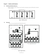
External Battery Cabinets
4 .3
External Power Cables Connecting
WARNING
WARNING
Verify polarity of connections. Risk of personal injury and damage to equipment from arc flash if
connections are reversed.
•
TURN OFF UPS AND DISCONNECT UPS FROM POWER SUPPLY BEFORE EBC INSTALLATION.
•
HIGH TOUCH CURRENT. EARTH CONNECTION MUST BEFORE CONNECTING SUPPLY. As a
result of the connected loads high leakage current is possible. Connection of the earth (ground) is
required for proper product operation. Do not check UPS operation by removal of the Earth (ground)
connection.
To install wires:
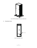
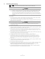
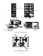
1. Remove the knock-outs in the left or right side plates on the EBC. See Figure 4-9. Refer to the applicable
UPS Installation and Operation manual or UPS cabinet conduit landing location.
2. Install conduit between the UPS cabinet and the EBC if needed. If installing a second EBC, install conduit
between the first and second EBCs.
3. Connect the positive (+) and negative (-) power wiring to the DC (+) and DC (-) terminals on EBC 1. Connect
the ground wiring to the ground terminal on EBC 1. See Figure 4-5.
4. Route and connect the other end of the battery cables (positive, negative, and ground) to the UPS DC (+),
DC (-) and ground terminals. Refer to the applicable Eaton UPS Installation and Operation manual or UPS
cabinet terminal locations and termination requirements.
5. Let the EBC stand side by side to the UPS and secure the DC battery cables to the EBC bottom base using
wire ties after all electrical connections have been completed.
6. If installing Double EBC (2 cabinets and one cabinet with breaker), proceed to Step 7-12.
7. Route the battery cables (positive, negative, and ground) from EBC 1(with breaker) DC and ground
terminals to EBC 2 DC and ground terminal blocks. See Figure 4-5,Figure 4-6 and Figure 4-9 for wiring
access information and terminal locations. See paragraph 3.2.2, Table 3-3 for wiring and termination
requirements.
8. Connect the positive (+) and negative (-) power wiring to the DC (+) and DC (-) terminals in EBC 2. Connect
the ground wiring to the ground terminal in EBC 2. See Figure 4-5.
9. Let the 2 battery cabinets stand side by side
10. Route the battery cables (positive, negative, and ground) from the UPS to the EBC 1(with breaker) DC and
ground terminal blocks. See Figure 4-5 and Figure 4-9 for wiring access information and terminal
locations. See paragraph 3.2.2, Table 3-3 for wiring and termination requirements.
11. Let the EBCs stand side by side to the UPS and secure the DC battery cables to the EBC bottom base
using wire ties after all electrical connections have been completed.
Wires enter/out from rear bottom or knock-out holes on 2 side plates.
NOTE
Summary of Contents for Single EBC
Page 1: ...External Battery Cabinets Installation and Operation Manual Eaton UPS Accessories...
Page 2: ......
Page 29: ...23 External Battery Cabinets Notes...
Page 34: ......
Page 35: ......
Page 36: ...614 01726 01...


