1 SmartWire-DT Gateway® EU5C-SWD-DP
1.4 Important data for engineering
SmartWire-DT Gateway EU5C-SWD-DP
01/13 MN120001Z-EN
www.eaton.eu
9
1.4 Important data for engineering
In connection with the SmartWire-DT modules, the gateway appears as a
modular module on the relevant field bus. The following gateway can be run
on the field buses specified below:
Each SmartWire-DT module is presented as a separate module, with its data,
to the field bus master.
The following number of SmartWire-DT modules is the maximum number
that can be run on the gateway:
Make sure to take the maximum volume of data that can be transmitted on
the field bus into account. The corresponding limit will be defined by the field
bus.
The SmartWire-DT line may be extended up to 600 m.
1.4.1 Field bus connection
The connection to the gateway uses a 9-pin D-sub socket. A standard PROFI-
BUS plug, e.g., ZB4-209-DS2, is used to connect to the field bus. This plug
features an integrated bus termination resistor that can be enabled and dis-
abled.
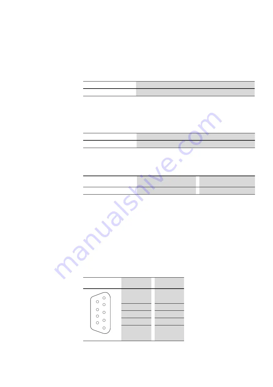
Figure 3:
Pinout for the PROFIBUS-DP terminal socket on the gateway
Gateway
Fieldbus
EU5C-SWD-DP
PROFIBUS-DP
Gateway
Maximum number of modules at the SWD line
EU5C-SWD-DP
58
Field bus-slave
Max. input data [Byte]
Max. output data [Byte]
PROFIBUS-DP
240
240
→
Information about the volume of input and output data of an
SWD module is provided in the Appendix of the manual "Smart-
Wire-DT Modules", MN05006001Z-EN.
PROFIBUS-DP
SUB-D socket
Signal
3
RxD/TxD-P
4
CNTR-P
5
DGND
6
VP (+5 V DC)
8
RxD/TxD-N
6
7
8
9
2
3
4
5
1


