6 Take STEP 7 into operation
6.8 Diagnostics
52
SmartWire-DT Gateway EU5C-SWD-DP
01/13 MN120001Z-EN
www.eaton.eu
6.8 Diagnostics
The system SmartWire-DT provides you with cyclic and acyclic diagnostic
information.
6.8.1 Cyclic diagnostics information
This basic diagnostic information is coded in the normal I/O map of each
SWD module. They provide information about whether the module partici-
pates in the normal data interchange via the SWD line. Furthermore, it is
reported whether any current diagnostic messages are pending. These two
information items are located in the first input byte in bit positions 4 and 6 for
all SWD modules. They permit fast and easy assessment of the condition of
the SWD module:
•
The SWD module is present and integrated actively into the SWD line.
•
The SWD module is operating fault-free.
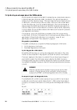
Example
The M22-SWD-K11-LED-R function element has a red LED for illuminated
pushbuttons and the two switch states 0 and 1. With cyclical input data of
one byte, it contains information on switch position and diagnostic informa-
tion.
Inputs:
Byte 0:
→
Please refer to the documentation of the PROFIBUS-DP master
XIOC-NET-DP-M in the manual MN05002002Z-DE "XIOC signal
modules" for basic information on the DP diagnostics.
You will find explanations there on access to the diagnostic data
of a DP slave module.
→
When using a Simatic S7, different system components may be
used to evaluate the module diagnostic function. For this refer
to the relevant documentation of the CPU or CP used.
7
6
5
4
3
2
1
0
Diagnostic data
Input data
SUBST
PRSNT
–
DIAG
–
–
NO1
NC1


