background image

Sonix 350-d Technical Manual

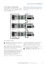
3.4.4  Hot Standby Bus and Hot Standby amplifi er

The Hot Standby ports provide a backup 100 V Line that 

will be used in the case of an amplifi er failure. It allows 

Hot Standby amplifi ers to drive the speaker load of any 

connected faulty 350-d unit.

The Hot Standby bus connections are only between the 

350-d units. Units are daisy-chained similarly to the Amp 

Bus. All connections are top port to bottom port, as per 

diagram below:

Hot Standby

Amp Bus

EOL-8 Bus

Fuse

Danger - Hazardous Voltages Present!

COMPLIANT

Amp

Fault

O/P

N/C

com

PSU

Fault

O/P

N/C

com

48 V

DC

I/P

+     -

Sonix 350-d

#3 Hot Stand-by

Hot Standby

Amp Bus

EOL-8 Bus

Fuse

Danger - Hazardous Voltages Present!

COMPLIANT

Amp

Fault

O/P

N/C

com

PSU

Fault

O/P

N/C

com

48 V

DC

I/P

+     -

Sonix 350-d

#2

Hot Standby

Amp Bus

EOL-8 Bus

Fuse

Danger - Hazardous Voltages Present!

COMPLIANT

Amp

Fault

O/P

N/C

com

PSU

Fault

O/P

N/C

com

48 V

DC

I/P

+     -

Sonix 350-d

#1

Hot Standby

Amp Bus

EOL-8 Bus

Fuse

Danger - Hazardous Voltages Present!

COMPLIANT

Amp

Fault

O/P

N/C

com

PSU

Fault

O/P

N/C

com

48 V

DC

I/P

+     -

Sonix 350-d

#6 Hot Stand-by

Hot Standby

Amp Bus

EOL-8 Bus

Fuse

Danger - Hazardous Voltages Present!

COMPLIANT

Amp

Fault

O/P

N/C

com

PSU

Fault

O/P

N/C

com

48 V

DC

I/P

+     -

Sonix 350-d

#5

Hot Standby

Amp Bus

EOL-8 Bus

Fuse

Danger - Hazardous Voltages Present!

COMPLIANT

Amp

Fault

O/P

N/C

com

PSU

Fault

O/P

N/C

com

48 V

DC

I/P

+     -

Sonix 350-d

#4

To Eol-8

To Eol-8

To Eol-8

To Eol-8

To Eol-8

To Eol-8

To Eol-8

To Eol-8

Figure 7. Hot Standby bus connections.

Warning:

 Hot Standby cables carry 100 V audio 

power line; Electrical Shock Risk warning labels 

need to be fi tted on both ends.

Any unit in a chain can be confi gured to be the Hot 

Standby amplifi er (see 5.5). The recommended location 

for placing the hot standby amplifi er is either above or 

below the bank of associated amplifi ers.

The Hot Standby amplifi er is not connected to the Eol-8 

unit, its top and bottom EOL-8 ports must be linked 

together instead, as per Figure 7 above. This connection 

is mandatory to enable 100 V output onto the Hot 

Standby bus and maintain the Healthy status of the 

system and is referred to as EOL loopback.

While there is no technical limit on how many amplifi ers 

a single Hot Standby amplifi er should support, practical 

considerations should be taken into account. Eaton 

suggests that a minimum of 1 and maximum of 8 

amplifi ers is a sensible starting point for a system.

ote: 

N

There can be more than one Hot Standby amplifier, each with its 

own chain of amplifiers connected in a Hot Standby loop.

Warning:

 Only confi gure one 350-d amplifi er as 

a Hot Standby per Hot Standby Bus loop.

13

SONIX 350-D TECHNICAL MANUAL  

TM367 / A  May 2022  www.eaton.com

Summary of Contents for SONIX 350-d

Page 1: ...ower Amplifier Fuse STATUS AC POWER SUPPLY Power Amp Earth Line Fan Temp Overload Shutdown Audio Output Local Ticktone Sense Test Local Reset DC PSU DC Battery Sonix 350 d hsb Line Call SonixTM 350 d Technical Manual ...

Page 2: ...E SPECIFICALLY SET OUT IN ANY EXISTING CONTRACT BETWEEN THE PARTIES ANY SUCH CONTRACT STATES THE ENTIRE OBLIGATION OF EATON THE CONTENTS OF THIS DOCUMENT SHALL NOT BECOME PART OF OR MODIFY ANY CONTRACT BETWEEN THE PARTIES In no event will Eaton be responsible to the purchaser or user in contract in tort including negligence strict liability or other wise for any special indirect incidental or cons...

Page 3: ...50 W Power Amplifier with 100 V line output Eol1 Sonix Remote End of Line unit Eol8 Sonix Amplifier to 100 V line interface unit 8 channel SP AD Sonix Intelligent loudspeaker monitoring unit Hmi Br Sonix intrinsically safe barrier ATEX IECEx for connecting Hmi 5 in explosive atmospheres Hmi Mute Sonix 100V loudspeaker mute Ex SA Hmi 26 Sonix Human Interface access panel Hmi 5 Sonix Small Human Int...

Page 4: ... Bus and Hot Standby amplifier 13 3 4 5 350 d power source 14 3 4 5 1 AC Input 14 3 4 5 2 48 V dc battery input 14 3 4 6 Fault outputs 15 3 4 6 1 PSU Fault 15 3 4 6 2 Amp Fault 15 3 4 7 Earth stud 15 3 4 8 Fusing 16 4 SETUP AND CONFIGURATION 16 4 1 Audio Gain 16 4 2 Unit ID Associated Zone 16 5 UNIT OPERATION 17 5 1 Front panel unit status indicators 17 5 1 1 Power 17 5 1 2 Amp 17 5 1 3 Earth 17 5...

Page 5: ...3 5 3 4 Line Cal 23 5 4 Audio broadcast 23 5 4 1 All Call 24 5 4 2 Post amp switching 24 5 4 3 Routine Speech disabled 25 5 5 Hot Standby amplifiers 25 5 5 1 Zones and Hot Standby amplifier 26 6 UNIT DE RATING 27 7 UNIT CUSTOMISATION 27 7 1 70 V Line output 27 8 COMMISSIONING TESTING 27 8 1 Before start 27 8 2 Fault finding 27 9 MAINTENANCE 29 5 SONIX 350 D TECHNICAL MANUAL TM367 A May 2022 www ea...

Page 6: ... 15 FIGURE 12 RECOMMENDED EARTH CONNECTION FOR THE UNIT 15 FIGURE 13 FRONT BUTTON OPERATION 19 FIGURE 14 TICKTONE TRAVEL OVER FAULTY LOUDSPEAKER LOOP 20 FIGURE 15 SENSE TEST SIGNAL WITH THE LOUDSPEAKER LOOP 20 FIGURE 16 FAILED SENSE TEST 21 FIGURE 17 SENSE TEST FOR A SPUR 100 V LINE CONFIGURATION 21 FIGURE 18 FAILED SENSE TEST WITH EOL 1 UNIT 22 FIGURE 19 RESTRICTED SENSE TEST TIMEOUT 22 FIGURE 20...

Page 7: ... monitors and supervises the amplifier loudspeaker cable installation and loop integrity with an inaudible signal The robust and industrial design of the 350 d amplifier ensures its protection against open or short circuit load deviation and abnormal loads associated with field loop faults Designed with safety in mind the 350 d automatically isolates its high voltage outputs if any cable is inadve...

Page 8: ...ly hazardous voltages currents confined spaces and potentially hazardous industrial environments Prior to undertaking any work please ensure relevant permits and regulations are adhered to 2 3 In the box 1 x Sonix 350 d Amplifier unit 1 x Technical Manual 2 4 Required tools Flat blade screw driver 0 6x3 5 for plug wiring M5 8mm Nut spinner or spanner Appropriate screw driver for cage nut fixings 2...

Page 9: ...Bus Fuse Danger Hazardous Voltages Present COMPLIANT Amp Fault O P N C com PSU Fault O P N C com 48 V DC I P 0 V 48 V Sonix 2Mx Hot Standby Amp Bus EOL 8 Bus Fuse Danger Hazardous Voltages Present COMPLIANT Amp Fault O P N C com PSU Fault O P N C com 48 V DC I P Hmi Bus Amp Bus Hmi Bus I O Bus 350 d COMPLIANT AC Input 85 265 vac 50 60Hz 110 or 230 V ac 50 60 Hz N C com N C com Power Amp Earth Line...

Page 10: ...ight it also requires to be installed on shelves or other weight support structure Stacking units is allowed for a maximum of three units due to the heat being generated while operating under full load To assist the air flow and cooling of the amplifiers the ventilation space of at least 1U is required before next unit either another 350 d or any other Sonix module can be mounted above Power Amp E...

Page 11: ...48 V DC I P Sonix 350 d 2 Hot Standby Amp Bus EOL 8 Bus Fuse Danger Hazardous Voltages Present COMPLIANT Amp Fault O P N C com PSU Fault O P N C com 48 V DC I P Sonix 350 d n Figure 4 Connecting single 350 d to 2Mx module View of rear of the units When connecting more than one Sonix 350 d unit the top port of the 2Mx is connected to the top port of the first 350 d unit while the bottom port of the...

Page 12: ... both ends Each individual amplifier connects to one set of ports on the Eol 8 unit no specific cable connection ordering required up to 8 amplifiers per Eol 8 unit If more than 8 amplifiers are required within the PA GA system additional Eol 8 units are required Hot Standby Amp Bus EOL 8 Bus Fuse Danger Hazardous Voltages Present COMPLIANT Amp Fault O P N C com PSU Fault O P N C com 48 V DC I P S...

Page 13: ... connections Warning Hot Standby cables carry 100 V audio power line Electrical Shock Risk warning labels need to be fitted on both ends Any unit in a chain can be configured to be the Hot Standby amplifier see 5 5 The recommended location for placing the hot standby amplifier is either above or below the bank of associated amplifiers The Hot Standby amplifier is not connected to the Eol 8 unit it...

Page 14: ...5 mm2 for each conductor in the 3 core power cable Figure 9 AC power input Warning Power cable must include an adequately sized Earth conductor connected to protective earth ote N As these cables are power feeds they should be where pos sible routed within the PA GA system in a separate way to avoid contact with dc power or audio cables and reduce the possibility of interference 3 4 5 2 48 V dc ba...

Page 15: ...7 Earth stud Each unit is equipped with an M5 earth stud at the back as a protection mechanism for the unit Each individual 350 d unit must be connected directly to the Protective Earth with at least 1 mm2 wire although 2 5 mm2 wire is recommended Figure 12 Recommended earth connection for the unit Warning Unit must be connected to protective earth observing minimum cable requirements Hot Standby ...

Page 16: ...d for quality and functionality testing and should be reconfigured as appropriate on first use Typical PA GA systems have more than one amplifier present it is not practical to pre configure replacement units before shipping as exact replacements Please refer to SAS Product Manual for details on how to import export or change the settings 4 1 Audio Gain LK1 and LK2 set the gain for the audio broad...

Page 17: ...can indicate up to four states Green Red Status On Off Healthy Off On Fault On Slow flashing Healthy but with historic now cleared fault Off Fast flashing Connection issues ote N Not all states are relevant for each pair of LEDs and some indi vidual LEDs may flash for specific functions see details below 5 1 1 Power This is a simple 48 V dc power indicator Green Status On DC Power present and ampl...

Page 18: ... Green Audio level low Orange Audio level in nominal range Red Audio level approaching maximum level 5 1 10 AC Power status Indicates status of the ac power supply Green Red Status On Off AC power present Off On AC power missing amplifier in fault On Slow flashing AC power was missing but is now restored ote N This indication will only work if the unit is supplied from both ac and battery power so...

Page 19: ...tion Hot Standby Amp Bus EOL 8 Bus Fuse Danger Hazardous Voltages Present COMPLIANT Amp Fault O P N C com PSU Fault O P N C com 48 V DC I P Sonix 350 d Out Amp 1 Return Amp 2 Sonix Eol 8 1 Loudspeaker Loop 1 2 3 21 kHz Line STATUS COMPLIANT Sonix 35 Ou Am Ret Am Line STATUS Hot Standby Amp Bus EOL 8 Bus Fuse Danger Hazardous Voltages Present COMPLIANT Amp Fault O P N C com PSU Fault O P N C com 48...

Page 20: ...nual for details ote N Locally initiated Ticktone will only play over the loudspeakers connected to that specific amplifier Please refer to Global Ticktone functionality inside the 2Mx Technical Manual for Ticktone played over all zones 5 3 2 Sense Test Sense Test is an integrity test for the 100 V loudspeaker line It is an inaudible amplifier generated 21 kHz pulse sent once over the connected sp...

Page 21: ...ker spur 2 EOL Device option needs to be set to ENABLED in the 350 d configuration ote N For details on connecting and functionality of Eol 1 unit please refer to the Eol 1 Product Manual For details on changing the configuration options please refer to the SAS Product Manual 3 Hot Standby Amp Bus EOL 8 Bus Fuse Danger Hazardous Voltages Present COMPLIANT Amp Fault O P N C com PSU Fault O P N C co...

Page 22: ... 2 2 Sense Test disable Disabling sense test in the 350 d configuration doesn t stop the testing rather it ignores the result and will not generate a line fault See the SAS manual for more details 5 3 2 3 Restricted Sense Test and audio breakthrough Although the sense test built into the Sonix 350 d has been carefully designed to be in audible some speakers do generate audible pops clicks and buzz...

Page 23: ...anger Hazardous Voltages Present COMPLIANT Amp Fault O P N C com PSU Fault O P N C com 48 V DC I P Zone 1 Subzone 2 ID 1 2 Hot Standby Amp Bus EOL 8 Bus Fuse Danger Hazardous Voltages Present COMPLIANT Amp Fault O P N C com PSU Fault O P N C com 48 V DC I P Zone 1 Subzone 1 ID 1 1 Audio Output Audio Output Audio Output To Eol 8 To Eol 8 To Eol 8 3 2 1 Zone 1 3 2 1 Zone 2 Zone 2 Broadcast Hot Stand...

Page 24: ...48 V DC I P ID 31 1 Sonix 350 d 1 Relay Bank Z1 Z2 Z3 Zone Controller All Call amplifiers are typically used as either a Hot Standby Amplifier or used in conjunction with Post Amplifier Switching see 5 4 2 5 4 2 Post amp switching A Sonix 350 d amplifier can be used to support multiple acoustic zones using Post amplifier switching This involves configuring an amplifier as All Call allowing it to b...

Page 25: ...xact configuration requirements to support this 5 4 3 Routine Speech disabled If 350 d is intended for a zone where Routine Speech is not desired i e accommodation it is possible to disable Routine Speech in the configuration The amplifier will then only respond to Important Message and Alarm broadcast requests See SAS Product Manual for details 5 5 Hot Standby amplifiers When a Sonix 350 d report...

Page 26: ...00 V audio path for two faulty amplifiers Sonix 350 d 3 Hot Stand by Sonix 350 d 2 Audio Output Sonix 350 d 1 Audio Output EOL 8 Bus To Eol 8 To Eol 8 EOL 8 Bus Because of this it is recommended that for the bigger systems there is one Hot Standby unit per maximum eight amplifiers 5 5 1 Zones and Hot Standby amplifier Normal Hot Standby amplifiers are configured as All Call amplifiers this allows ...

Page 27: ...Connection of each cable to and from the system is correct and the cables are not damaged DC battery input if used has the correct polarity Unit is correctly earthed All connections are fully inserted There are no short circuits between negative and positive conductors 8 2 Fault finding This is intended to be a quick reference guild to possible reasons for the amplifier to be a set state No indica...

Page 28: ...verload indicator Green Slow Flashing Red Previous overload fault seen Red Unit has detected a load that is beyond its safe output capabilities likely a short circuit Unit will auto reset after 10 seconds Isolate amplifier from external loudspeaker lines should show if fault is internal or external to the PA GA rack Internal faults will need more careful investigation and possible amplifier replac...

Page 29: ...um care and it is advisable that it will be performed monthly Check the unit for visible damage scratches or bumps Check unit fixing to the rack tighten loose screws Check connections and cable integrity replace damaged cables Remove dust and dirt from front panel clean with a dry cloth ote N Do not use sharp objects water aggressive cleaning agents or solvent to clean the unit 29 SONIX 350 D TECH...

Page 30: ...aton and SONIX are registered trademarks All other trademarks are property of their respective owners Changes to the products to the information contained in this document and to prices are reserved so are errors and omissions Only order confirmations and technical documentation by Eaton is binding Photos and pictures also do not warrant a specific layout or functionality Their use in whatever for...

Reviews: