


10
Sonix Pbx Technical Manual
SONIX PBX TECHNICAL MANUAL
TM372 / A June 2022 www.eaton.com
3.3 Installation and connectivity
The Pbx is designed to be mounted within industry
standard 19” frames within the telecoms or PA/GA
cabinet. The Pbx is attached to the 19” frame within the
cabinet by the four mounting holes on the front panel.
Care should be taken to ensure no ventilation points are
obstructed and that the product is correctly supported
within the cabinet.
The Pbx unit can be connected to the system in two
significant ways:
•
Directly on the Sonix PA/GA system’s IO-Bus via CAT
6A cabling
•
Into the Sonix PA/GA systems’ lo-Tu module via audio
and key line using two twisted pair cables
If the Pbx is connected directly to the system via the
IO-Bus, it can monitor system status and will ‘hold’ the
message while the system is busy until the system is
ready, or message has timed out.
Prior to connecting any field cables to the Pbx they must
be checked and recorded for the following
•
All power and signal conductors free from Earth.
•
Correct voltages are provided on power and signal
cables
All faults must be rectified prior to connecting to the
unit, with attention to cable polarity.
3.3.1 RJ45 Audio and data system connections
When the Pbx is installed as an integral component
within the cabinet, it connects to the 2Mx matrix via the
IO bus. These are identified by the blue CAT 6A cables
which connects the rear of the 2Mx with the Pbx using
the RJ45 connectors. The IO bus is usually connected
as a loop from the 2Mx to provide redundant paths for
the control data, status data and audio should they be
needed.
A second set of RJ45 connectors provides a full
duplicate audio and data path to a second 2Mx (usually
the B-side system) for redundancy.
Bus
Name
Colour
Connected to
Data type
IO Bus
Blue
Io, MS12, & PBx
units
Transmit
Unit control, status
data + Active system
Audio
Receives System control and
status data
Table 3 – IO Bus description
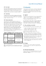
3.3.2 Telephone interface connections
A 5-way connector provides the interface to the on-
site telephone system operating as a either a 2-wire or
2-wire E&M telephone connection. The unit’s 2-wire
interface mimics a standard analogue telephone.
Cable Specification
Type
Description
Label 1
Label 2*
2off Twisted pair,
individual and overall
screen.
0.25 mm² to 0.5 mm²
(ferrules with sleeve)
0.25 mm² to 1.5 mm²
(ferrules without sleeve)
Input
2-wire A
A1
K1
Input
2-wire B
A2
K2
---
Screen
SCN
SCN
Input
E&M line 1
K1
A1
Input
E&M line 2
K2
A2
Table 4 – Telephone interface description
ote:
N
E&M line 1 and E&M line 2 are connected to volt free contacts.
ote:
N
* Label 2 refers to incorrect labelling on older units
Typical wiring connections
Figure 3 – Telephone interface
R
Sonix Pbx
TM
LOCAL STATUS
POWER SUPPLY
OPERATIONAL
Fuse
Cancel
Zoned / Global
Source Select
Reset
DC PSU
2w
E+M
2w
Global
Message
Zoned
Message
Message
Cancel
Monitor
Active
Pbx
playback
Pbx
record
Power
8
7
6
5
4
3
2
1
Pbx I/P
MONITOR
A SIDE O/P
B SIDE O/P
48V
DC
I/P
+ -
Fault
O/P
N/C
Com
K1 K2 SCN A1 A2
I/O Bus A
I/O Bus B
A1 A2 SCN COM N/C
A1 A2 SCN K1 K2
A1 A2 SCN K1 K2
COMPLIANT
7
6
5
4
3
2
1
2-Wire connection
Screen
E&M connection (optional)
Push button connection
Screen
Loudspeaker connection
Keyline connection
Screen
Audio connection
Power connection
0Vdc (-)
48Vdc (+)
General fault connection
N/C
Com
Pbx I/P
Primary Unit ID 1
Secondary Unit ID 2+
2 wire
Telephone I/F
Pbx I/P
K1 K2 SCN A1 A2
K1 K2 SCN A1 A2


