background image

11

Sonix Pbx Technical Manual

SONIX PBX TECHNICAL MANUAL  

TM372 / A  June 2022  www.eaton.com

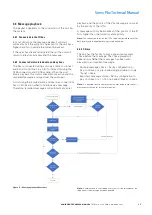
Message monitoring and abort connections 

A 5-way connector provides the interface to local 

loudspeaker for listening to the message being recorded 

and for a push button to prevent the message from 

broadcasting if required. 

Cable Specification

Type

Description

Label

2off Twisted pair, individual and 

overall screen. 

0.25 mm² to 0.5 mm² (ferrules with 

sleeve)

0.25 mm² to 1.5 mm² (ferrules 

without sleeve)

Output

Audio output

A1

Output

Audio output

A2

---

Screen

SCN

Input

Keyline 1

COM

Input

Keyline 2

N/C

Table 5 – Message monitoring interface description

Typical wiring connections

Figure 4 – Message monitoring and abort

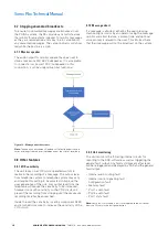
3.3.3  Isolated audio and key line connections

Two 5-way connectors provide a duplicated interface for 

isolated audio and control lines for connection to other 

third party equipment operating alongside the RJ45 

connections. These interfaces can be used to replace 

the RJ45 connections provided they are connected to 

an IO Tu unit’s audio input, usually when installed in a 

separate cabinet with PABx equipment.

Cable Specification

Type

Description

Label

2off Twisted pair, individual and 

overall screen. 

0.25 mm² to 0.5 mm² (ferrules with 

sleeve)

0.25 mm² to 1.5 mm² (ferrules 

without sleeve)

Output

Audio output

A1

Output

Audio output

A2

---

Screen

SCN

Output

Keyline 1

K1

Output

Keyline 2

K2

Table 6 – Audio & Key line interface description

Typical wiring connections (A-side & B-side

)

Figure 5 – Isolated audio and Keyline outputs

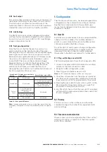
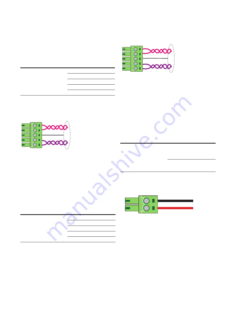
3.3.4  Power connections

The Sonix Pbx is powered via a 2-core 48 V dc input 

on the rear of the unit. This input should be connected 

to the managed 48 V dc power output from the Sonix 

PM10 power management unit. 

Note: As these cables are power feeds they should 

be routed within the PA/GA system in a way so as to 

avoid contact with signal or audio cables and other high 

voltage cables.

Cable Specification

Type

Description

Label

2off Twisted pair, individual and 

overall screen. 

0.25 mm² to 0.5 mm² (ferrules with 

sleeve)

0.25 mm² to 1.5 mm² (ferrules 

without sleeve) 

Input

+48Vdc

+

Input

0Vdc

-

Table 7 – Power interface description

DC Power connection

Figure 6 – Power connections

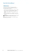
3.3.5  General fault output connections

The general fault output is a low voltage, volt free 

contact output. The output can be set in configuration 

to either normally open or normally closed. It is 

recommended that the output is set to normally closed 

so a loss of power to the unit will be detected.

R

Sonix   Pbx

TM

LOCAL STATUS

POWER SUPPLY

OPERATIONAL 

Fuse

Cancel
Zoned / Global
Source Select
Reset

DC PSU

2w

E+M

2w

Global

Message

Zoned

Message

Message

Cancel

Monitor

Active

Pbx

playback

Pbx

record

Power

8

7

6

5

4

3

2

1

Pbx I/P

MONITOR

A SIDE O/P

B SIDE O/P

48V

DC

I/P

+    -

Fault 

O/P 

N/C 

Com

K1 K2 SCN A1 A2

I/O Bus A

I/O Bus B

A1 A2 SCN COM N/C

A1 A2 SCN K1 K2

A1 A2 SCN K1 K2

COMPLIANT

7

6

5

4

3

2

1

2-Wire connection

Screen

E&M connection (optional)

Push button connection

Screen

Loudspeaker connection

Keyline connection

Screen

Audio connection

Power connection

0Vdc (-)

48Vdc (+)

General fault connection

N/C

Com

Pbx I/P

Primary Unit ID 1

Secondary Unit ID 2+

2 wire

Telephone I/F

Pbx I/P

K1 K2 SCN A1 A2

K1 K2 SCN A1 A2

Summary of Contents for SONIX Pbx

Page 1: ...SONIXTM Pbx Record and Replay Unit SonixTM Pbx Technical Manual...

Page 2: ...FOR A PARTICULAR PURPOSE OR MERCHANTABILITY OTHER THAN THOSE SPECIFICALLY SET OUT IN ANY EXISTING CONTRACT BETWEEN THE PARTIES ANY SUCH CONTRACT STATES THE ENTIRE OBLIGATION OF EATON THE CONTENTS OF T...

Page 3: ...feedback 2Mx Sonix 2Mx Central controller Amp 350 d Sonix 350 W Power Amplifier with 100 V line output Eol1 Sonix Remote End of Line unit Eol8 Sonix Amplifier to 100 V line interface unit 8 channel SP...

Page 4: ...er connections 11 3 3 5 General fault output connections 11 4 UNIT OPERATION 12 4 1 Data and audio communications 12 4 1 1 PA GA mounted using CAT6A cabling 12 4 1 2 PA GA mounted using isolated audio...

Page 5: ...1 Monitor speaker 18 4 7 2 Message abort 18 4 8 Other features 18 4 8 1 VOX sensitivity 18 4 8 2 Unit monitoring 18 4 8 3 Fault output 19 4 8 4 Link Settings 19 4 8 5 Front panel operation 19 5 CONFIG...

Page 6: ...ONT PANEL INDICATIONS AND CONTROLS 9 TABLE 2 REAR PANEL CONNECTORS 9 TABLE 3 IO BUS DESCRIPTION 10 TABLE 4 TELEPHONE INTERFACE DESCRIPTION 10 TABLE 5 MESSAGE MONITORING INTERFACE DESCRIPTION 11 TABLE...

Page 7: ...ging to protect the goods during transit Please ensure that once unpacked checked and installed that all packaging is disposed recycled in a responsible manner 2 3 ESD Electro Static Discharge The Son...

Page 8: ...systems The unit occupies a standard 1U 19 rack footprint within the cabinet User access to the unit is through calling the assigned extension number connected to the Pbx i p and allowing the unit to...

Page 9: ...t Reset DCPSU 2w E M 2w Global Message Zoned Message Message Cancel Monitor Active Pbx playback Pbx record Power 8 7 6 5 4 3 2 1 Pbx I P MONITOR A SIDE O P B SIDE O P 48V DC I P Fault O P N C Com K1 K...

Page 10: ...us is usually connected as a loop from the 2Mx to provide redundant paths for the control data status data and audio should they be needed A second set of RJ45 connectors provides a full duplicate aud...

Page 11: ...s A side B side Figure 5 Isolated audio and Keyline outputs 3 3 4 Power connections The Sonix Pbx is powered via a 2 core 48 V dc input on the rear of the unit This input should be connected to the ma...

Page 12: ...ue to operate without any loss of functionality A flashing IO fault is logged on the 2Mx status display to warn of the fault and differentiate it from any other internal cable loop fault 4 1 2 PA GA m...

Page 13: ...ff 2 wire E M operation not configured or available Solid green Set for 2 wire E M operation Flashing options Front panel configuration see section 4 8 5 Table 12 2 wire E M LED description 4 2 6 Zone...

Page 14: ...condary unit interconnection Once the unit has answered the user will be instructed to follow a series of prompts or messages to enter zoning information or be directed to leave a message see sections...

Page 15: ...ecific zones the user enters the required zoning information when indicated by the unit according to the flow chart below Each zone requested is entered using the telephones key pad as shown below Zon...

Page 16: ...imited to 120 seconds of audio The user can cancel the message by pressing or press to start playback at any time during the recording On finishing leaving a message the user can hang up or leave the...

Page 17: ...when to hold queue a message Therefore recorded messages will automatically enter playback and the priority of the Pbx message is now set by the priority of the IO Tu A message will only be broadcast...

Page 18: ...ort tone a series of bleeps relayed over the telephone at the start of recording 4 8 Other features 4 8 1 VOX sensitivity The unit relies on a VOX voice operated switch to maintain the recording of a...

Page 19: ...tus ote N Changing either zoned or source via the front panel will only be a temporary change and will revert to stored configuration on a power cycle 5 Configuration The Pbx like most Sonix units has...

Page 20: ...nit for visible damage scratches bumps Check connections and cable integrity replace damaged cables tighten terminal connectors loose screws Check unit fixing to the rack tighten loose screws Remove d...

Page 21: ...21 Sonix Pbx Technical Manual SONIX PBX TECHNICAL MANUAL TM372 A June 2022 www eaton com...

Page 22: ...aton and SONIX are registered trademarks All other trademarks are property of their respective owners Changes to the products to the information contained in this document and to prices are reserved s...

Reviews: